Element holders and other hardware.
|
Screws, washers, nuts, element holders
There are 16 element holders (1) in total, each with matching M5 screw,
lockwasher, and nut.
The self-tapping screw (2) will help fasten the quad-element to the
boom.
Two big washers (3), two wing nuts (4), and two M6 screws (5) plus two
washers from the pile (6) will be used for the mast clamp. Remaining parts
belonging to the mast clamp are not in the photo.
|
|

Center of the quad element.
|
Quad element
This photo shows the center of the quad element. The two N-connectors
are designed for easy change of polarization. By using connector 1a, horizontal
polarization is achieved. Connector 4a provides vertical polarization.
LHCP or RHCP is achieved using both connectors and a phase cable.
The center pin of connector 1a is connected to alu-band 1. The center
pin of connector 4a is connected to alu-band 4. Alu-band 2 must be fastened
to the boom using a self tapping screw. Alu-band 3 is factory-mounted.
The two factory-mounted screws (5) penetrate the alu-box and are intended
for going through two holes in the boom. The two screws (5) are fixed and
cannot be turned.
|
|

The quad elementet mounted on the boom.
|
Mounting the quad element
The quad element is attached to the boom using two lockwashers and
two M5 nuts(1). The self tapping screw (2) is used for fastening the alu-band
to the boom. But before doing that, a new hole was drilled - the factory
made hole was not properly placed.
Fitting the quad element can be a challenge. Be
patient, and do not use excessive force!
|
|

The quad element is attached to the boom.
|
The quad element attached
This photo shows how the quad element is attached to the boom. |
|
 |
Reflector; part 1/2
The reflector elements are mounted on the element holders and fastened
by a screw, a lockwasher, and a nut. The element holders are mounted closest
to the boom. The element holders secure, that the reflector elements are
kept properly in place.
Mounting sequence:
nut - lockwasher - reflector element - element holder - boom - element
holder - reflector element - screw
|
|
 |
Reflector; part 2/2
This photo shows the reflector from a different angle. The two element
holders are mounted on the boom and they keep the two reflector elements
in place.
All director elements are mounted in the same
way. |
|
 |
Mast clamp; step 1/3
First step is to put the U-bolt through the two holes in the fixed
clamp. |
|
|
 |
Mast clamp; step 2/3
The second step is to mount the boom clamp (marked Wimo) on the fixed
clamp using two M6 screws. |
|
|
 |
Mast clamp; step 3/3
The third step is to add the latch to the U-bolt. Add two M6 big washers,
and finally two M6 wing nuts. Done! |
|
 |
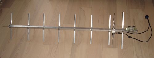
The finished antenna with phasing lines. |
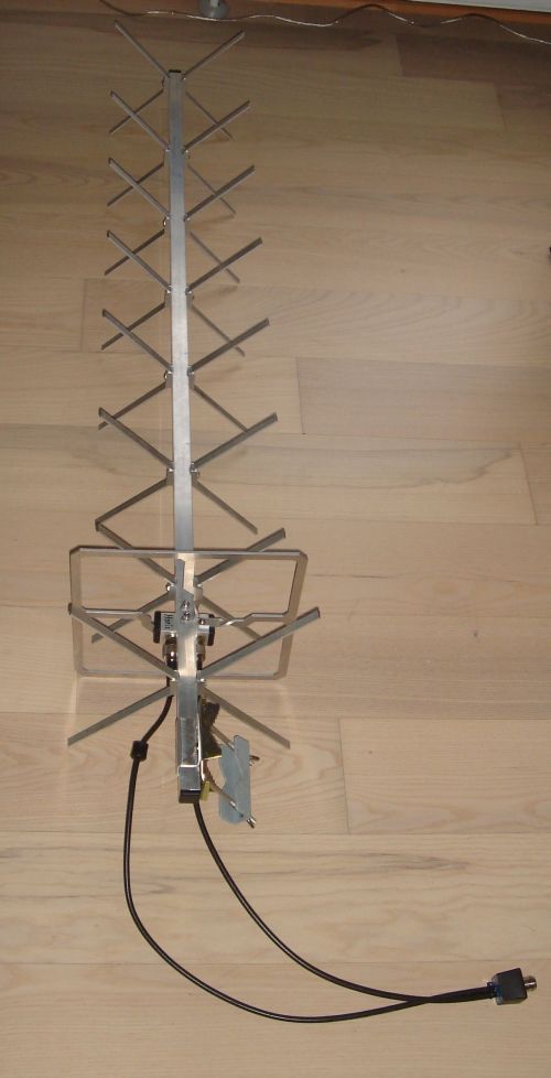
 | Close-up of the finished antenna.
The longest phasing line is connected to the leftmost N-socket to obtain RHCP. |


