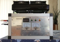
Fig. 1. Hardware configuration for 144 MHz EME.
Refer to figure 1. Coax-Relay1
is a 250 W coax-relay (Tohtsu CX-140). Coax-Relay2 is a 1 kW
coax-relay (Tohtsu CX-600) sitting in a plastic box near the antenna. The bias-T is from Wimo.de, and the
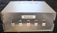
sequencer is homemade. The preamp is
Extra-2 from
HA8ET with typ. 0.5 dB NF. When 12V DC is applied to the
bias-T via Port1, the preamp is in receive mode. During transmit, 12V DC is removed from the Bias-T and
a relay in the preamp shorts the input port to ground thus
protecting the electronic circuit. The
preamp is housed in a water-resistant box mounted near the antenna.
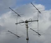
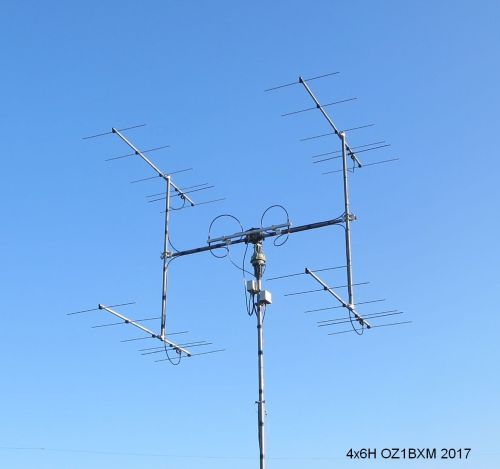
Fig. 2. My 4x6H antenna array for 144 MHz EME.
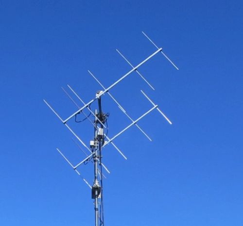
My antenna
array for 144 MHz is 4x6H which is four stacked 6-element yagi-antennas
PA144-6-2
with
horizontal polarization. The stacking distance is 1.90 m horizontal and 1.90
m vertical. These distances are shorter than the factory
recommended which are 2.40 m horizontal and
2.20 m vertical. All four antennas are mounted on an H-frame made
of 1½" aluminium tubes.
The
power splitter is fitted using a
homemade clamp. The four cables between the antennas and the power
splitter are of same type (LMR400) and they have the same physical
length (3.00 m each). The two grey boxes contain Coax-Relay 2 and the preamp.
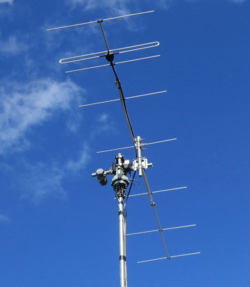
Antenna mast
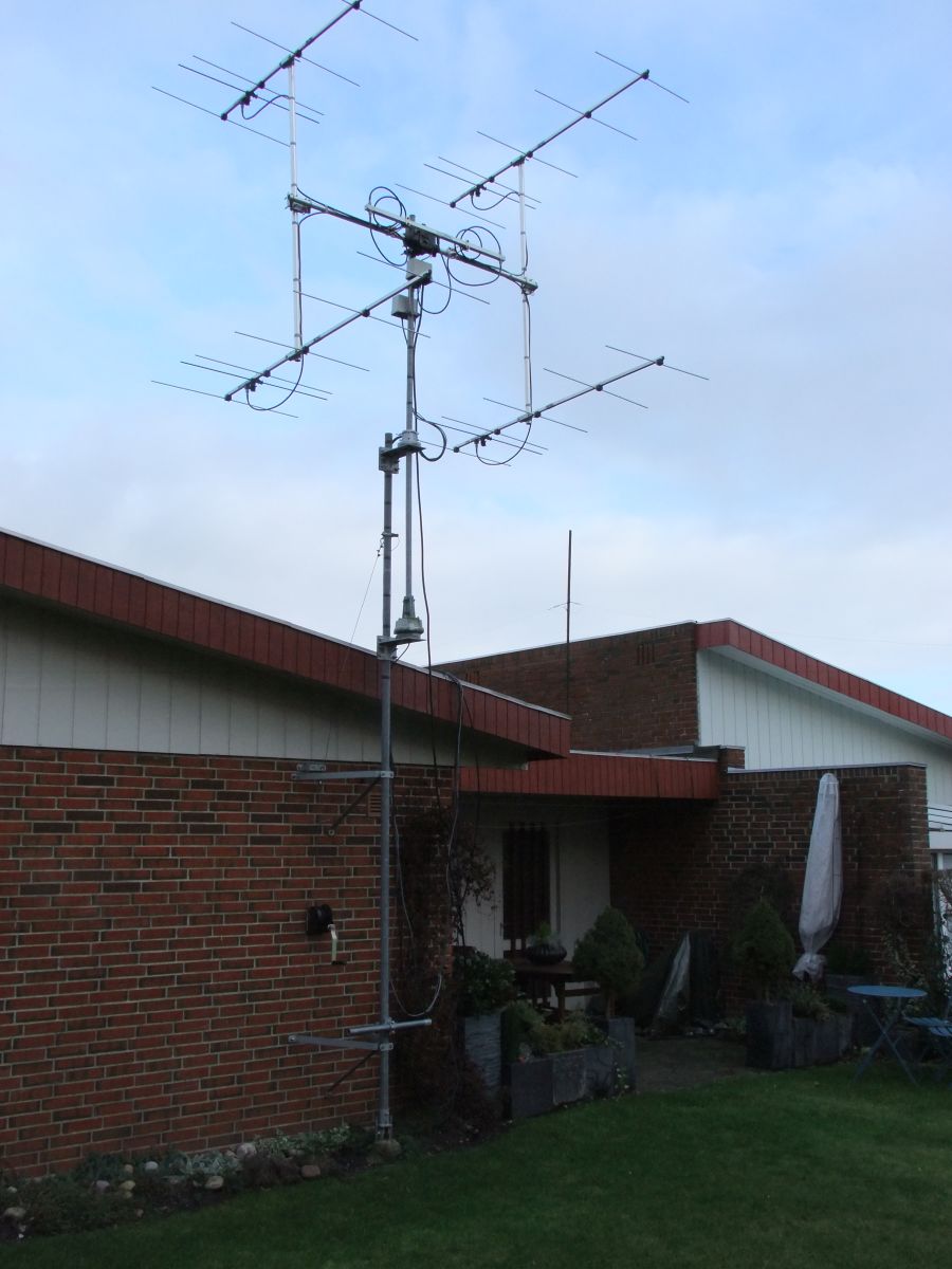
Fig. 3. Antenna mast.
The
lower tube is 2" steel, and it is attached to the house wall
using 2 common antenna brackets. Tube length is 4 meters.
This tube can be "laid down" on the lawn using the winch on the
brick wall,
a steel wire, and a pulley.
The upper tube is 1½" steel and the length is
2.5 m. Two
PLS50
platforms from
UKW-Berichte are attached to the lower tube and holds the upper tube. The lower
platform supports a Yaesu G-600 rotor, and the upper
platform supports a thrust bearing
KS065.
Rotor system
You
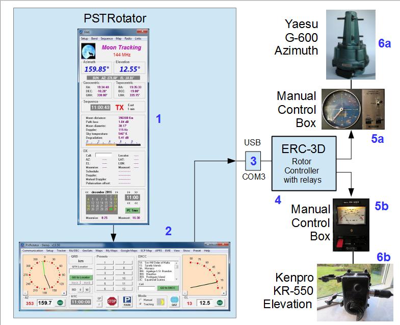
can view my rotor system in fig. 4. The antenna
is turned horizontally with a Yaesu G-600 rotor (6a),
and elevated with a Kenpro KR-550 (6b). Both rotors are controlled
by the ERC-3D rotor controller (4) which interface the 2 control
boxes (5a
and 5b) using several relays. The relays are inside the ERC-3D box. The
controlling software is PSTRotator (2). PSTRotator has a
separate window dedicated to Moon tracking (1). The
interface between the PC and the Rotor Controller is a
USB-to-serial converter (3).
Fig. 4. How the rotors are controlled by PSTRotator.
PSTRotator (2) runs on my Windows 10 computer. PSTRotator receives Az/El data from
WSJT
(not in the figure). The main window (2) shows the position of the
two rotators. The green arrow points at the current rotator
position, and the black arrow points at the "go to" position.
There is a dedicated window for EME (1) in PSTRotator. The
rotor controller (4) is under the control of PSTRotator via a
serial USB-interface (3). The rotor controller (4) contains
4 relays, which are used for "pressing buttons" inside the
two control boxes (5a and 5b). The buttons UP, DOWN, RIGHT, and LEFT are
controlled by the ERC-3D rotor controller (4). The rotor controller
receives position data from the rotors (a voltage between 0
and 5 V DC). The rotor controller will "release the button" when
the rotor (6a or 6b) has turned the antenna to the proper position.

