Kenwood TS-850 repair


New DC-DC board solves the ALC problem

DC-DC board circuit diagram
Original DC-DC board circuit diagram.

The ALC problem 
Kenwood TS-850 can develop an ALC problem. The ALC voltage becomes unstable and swings up and down, and so does the TX output. The RX works fine, but the TX becomes unusable. You can watch this video to experience the problem. 

The ALC voltage is created by the DC-DC board (X59-1100-00), which is a tiny daughter-board sitting on top of the RF unit (X44-3120-00). The DC-DC board creates a negative, constant ALC voltage (-6 V). This task is accomplished by generating AC (transistors Q1-Q3 oscillate at 15 kHz), which is rectified by D1 and stabilized by the zener diode D605.

There are 2 errors in the partial diagram to the left: The polarity of C626 and C628 are reversed. However, it seems that Kenwood actually mounted both of them correctly on the PCB!

Repair methods 
Several repair methods have been described on the Internet. One is to lower R2 and R3 from 22 kohm to 18 kohm. I have tried this method, and it lasted 10 month, then the problem came back. Another repair is to replace Q1-Q3 with better transistors. 

I've solved the ALC problem by building a replacement DC-DC board using modern components.


New circuit diagram
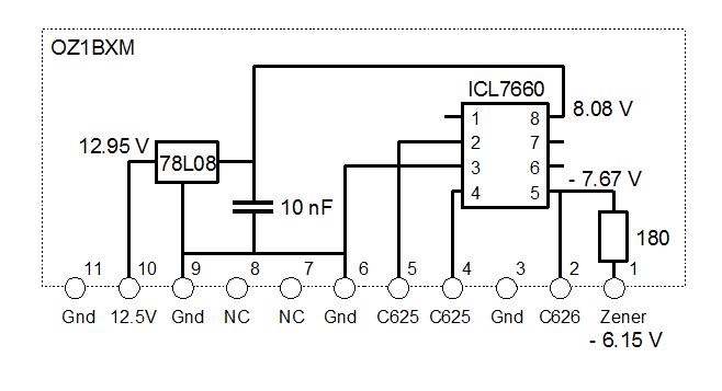
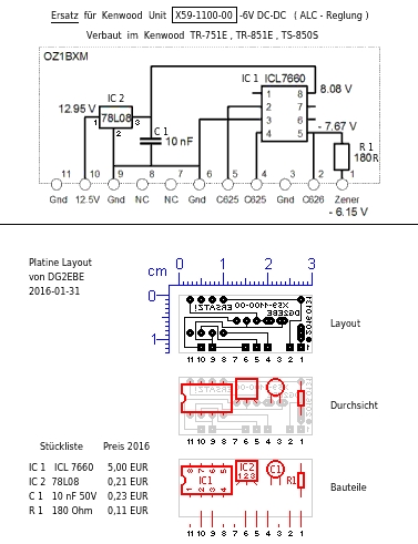
Circuit diagram of the replacement DC-DC board.

Replacement circuit

ICL7660 is a voltage inverter. Two capacitors (C625 and C626, each 10 uF) are needed for creating a negative voltage output. The negative output will be at the same voltage level as the positive supply voltage. This means, that +8V supply voltage at pin 8 will create -8V output voltage at pin 5. The 180 ohm resistor limits the current through the zener diode. The current is about 8 mA.

The ICL7660 version I used was ICL7660CPAZ from Intersil. This components is not critical at all, and versions from other vendors will do fine. The ICL7660A will do fine, too.

The input voltage to the DC-DC board 
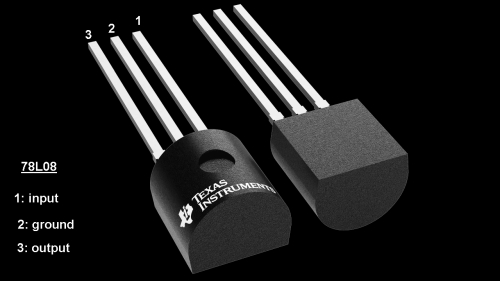
(12.5 V at pin 10) is stabilized by a 78L08 voltage regulator. The output from 78L08 is 8 V, which is the supply voltage of ICL7660. 

Credit to Yamada Radio Clinic, who inspired me to create this circuit.


Replacement DC-DC board, front view
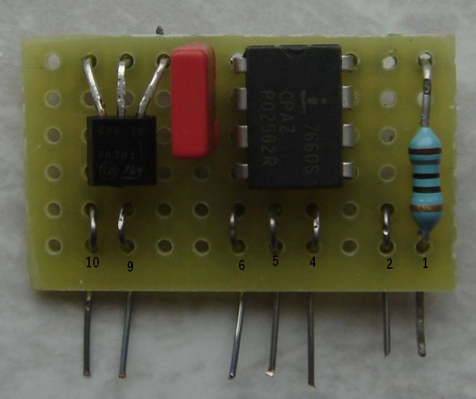
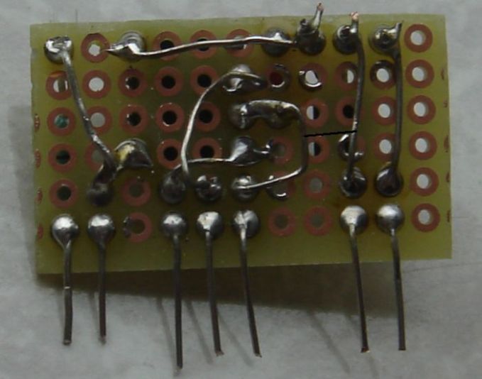
Replacement board, front side.
Replacement board, front side 

The replacement board is populated by 4 components. They are soldered on the rear side and wired together. This construction method is easy for small circuits.

The 7 pins at the bottom are solid wires. The pins will eventually be soldered to the RF board and they must be able to withstand heat from the soldering iron. That is why I have added a "half loop" on each of them. Each pin is soldered to the board in two places.  


Replacement board, rear side
Replacement board, rear side.
Replacement board, rear side
This picture shows how the component pins are soldered to the copper islands and  interconnected with solid wire. 

A wire was missing when I took the picture. The wire is indicated by a black line.
 
The replacement board measures 30 mm x 20 mm.
 

The replacement board is mounted
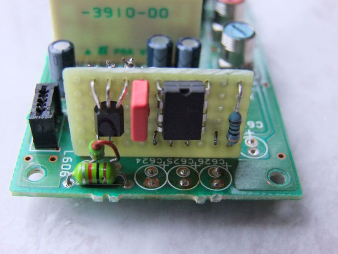
The replacement DC-DC board is mounted on the RF board.
Replacement board mounted on the RF board
Electrolytic capacitors C624, C625, C626, and C628 were first removed to create workspace. The old DC-DC board was then unsoldered and discarded.  

This picture shows how the replacement board is soldered to the RF board. The 4 electrolytic capacitors were fitted later. C625 and C626 were replaced by 10 uF types. 

Once you power up the Kenwood TS-850 the voltages indicated in the circuit diagram should be verified. 


PCB 
DG2EBE has made a PCB layout for the replacement board. It is shown below. Thank you Karl-Heinz!

pcb layout
                PCB for the replacement board.

The IC2 pins are shown in the figure below. IC2 is fitted with the flat side down.
78L08 pins
                                        78L08 pinout.

Revised by OZ1BXM Lars Petersen 24-Febr-2022. 

Home