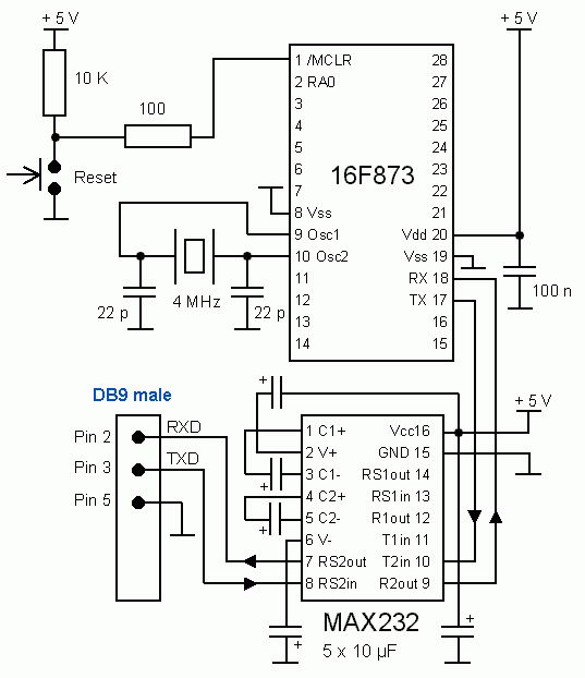
Testboard K3 configured for 873uart.asm
Hardware
The testboard K3 is set up with
reset circuit, crystal oscillator at 4 MHz and a MAX232 for RS232 communication. The 5 capacitors connected to MAX232 can
have a smaller value than shown in the circuit diagram, for example 1 uF
each. If you use MAX232A or ST232, they can be 100 nF types. The 4 arrows in the circuit diagram indicate signal direction.

Testboard K3 configured for 873uart.asm
Software in assembler
;************************************************************************
; Processor: PIC16F873
at 4 MHz
; Function: Characters
received via RS232 (19200 baud 8-N-1) are echoed
; Hardware: Testboard
K3
; Filename: 873uart.asm
Version 1.2
; Author: Lars Petersen, oz1bxm@pobox.com
; Credit:
Tony Nixon's 16F877 setup program at
;
http://www.piclist.com/techref/microchip/16f877/setup.htm
; History:
Ver 1.2 Added GOTO Start at 0x0000 to support bootloader
;
Ver 1.1 Replaced clrf STATUS with bcf STATUS,RP0 in TransWt
;
Ver 1.0 Initial release
;*************************************************************************
list P = 16F873
include "P16f873.inc"
__config _CP_OFF & _XT_OSC & _WDT_OFF & _PWRTE_ON & _LVP_OFF & _BODEN_ON
CBLOCK 0x20 ;Declare variable address
dataL
ENDC
;
; -----------
; INITIALIZE
; -----------
;
org 0x0000
goto Start
; Jump to Start
org 0x0004
Start movlw
0x00
movwf PORTA
; Initialize port A
movlw 0x00
movwf PORTB
; Initialize port B
movlw 0x40
movwf PORTC
; Initialize port C
bsf STATUS,RP0 ;
RAM Page 1
movlw 0x00
movwf TRISA
; All pins port A output
movlw 0x00
movwf TRISB
; All pins port B output
movlw 0x80
movwf TRISC
; All pins port C output except RC7/RX
;
; -------------------------
; FUNCTION OF PORT A
PINS
; -------------------------
;
movlw 0x06
; All pins digital I/O
movwf ADCON1
;
; ------------------------------------
; SET BAUD RATE TO COMMUNICATE
WITH PC
; ------------------------------------
; Boot Baud Rate = 19200,
No Parity, 1 Stop Bit
;
movlw 0x0C
; 0x0C=19200 baud (0x19=9600 baud)
movwf SPBRG
movlw b'00100100' ; brgh = high (2)
movwf TXSTA
; enable Async Transmission, set brgh
movlw b'10010000' ; enable Async Reception
bcf STATUS,RP0 ;
RAM Page 0
movwf RCSTA
;
; ------------------------------------
; PROVIDE A SETTLING
TIME FOR START UP
; ------------------------------------
;
clrf dataL
settle decfsz
dataL,F
goto settle
;
movf RCREG,W
movf RCREG,W
movf RCREG,W
; flush receive buffer
;
; ----------
; MAIN LOOP
; ----------
;
Main
call Receive
; wait for a char
movwf TXREG
; echo data back to sender
call Transwt
; wait until finished sending
goto Main
;
; ----------------------------
; RECEIVE CHARACTER
FROM RS232
; ----------------------------
; This routine does
not return until a character is received.
;
Receive btfss PIR1,RCIF
; (5) check for received data
goto Receive
movf RCREG,W
return
;
; ------------------------------------
; WAIT UNTIL RS232 IS
FINISHED SENDING
; ------------------------------------
;
TransWt bsf STATUS,RP0
; RAM Page 1
WtHere btfss TXSTA,TRMT
; (1) transmission is complete if hi
goto WtHere
bcf STATUS,RP0 ;
RAM Page 0
return
END
Remarks
The MAX232 is used for RS232 communication.
A simpler circuit can be set up using DS275, see the homepage of Wichit
Sirichote from Thailand. A terminal program (HyperTerminal) is set
up for 9600 baud with 8 data bits, no parity, no flowcontrol and 1 stop
bit.
The same program written in C is here.
Download
Download 873uart.zip
containing the source code in assembler and the hexfile.
Credit
Tony Nixon's UART test program at
http://www.piclist.com/techref/microchip/16f877/setup.htm
was my source for the above program. Thanks!