Balanced Antenna Tuner
QRP tuner for 10-40 meters by OZ1BXM
My homemade antenna tuner has three functions:
- Stockton Power Meter
-
Dummy load 25 W
-
Balanced antenna tuner
The tuner is kept in-line all the time.
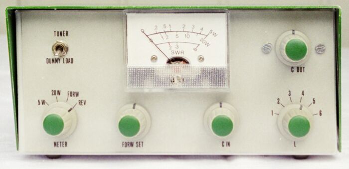
Figure 1. Front view.
| Knob |
Function |
| TUNER/DUMMY LOAD |
This is the function selector switch.
Position Tuner: input signal goes to tuner via Stockton Power Meter
Position Dummy load: input goes to dummy load via Stockton Power Meter |
| METER |
5W: Measure power. Maximum meter deflection is 5 W.
20W: Measure power. Maximum meter deflection is 20 W.
FORW: Measure forward power (input power)
REV: Measure reverse power (reflected power) |
| FORW SET |
Adjust to maximum meter deflection when the METER switch
is in the FORW position. |
| Cin |
Antenna tuner adjustment |
| L |
Antenna tuner adjustment (Lout) |
| Cout |
Antenna tuner adjustment |
The different blocks are seen in fig. 2 (left picture). Please compare with the photo
in fig. 3.
Figure 2. Left: Physical block diagram. Right: How the blocks
are connected
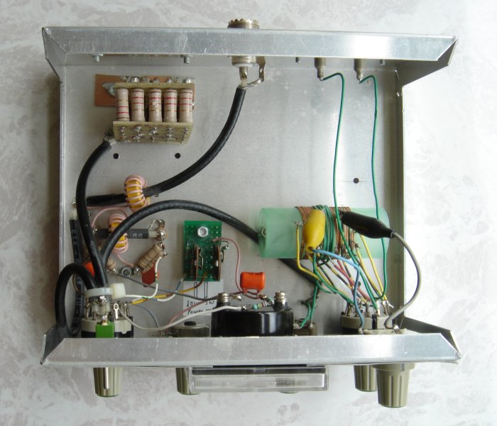
Figure 3. Top view.
Stockton Power Meter
The Stockton power meter was originally described by G4ZNQ David Stockton in SPRAT (the journal of G QRP Club). The power meter is simple to build and has low insertion loss and good accuracy.
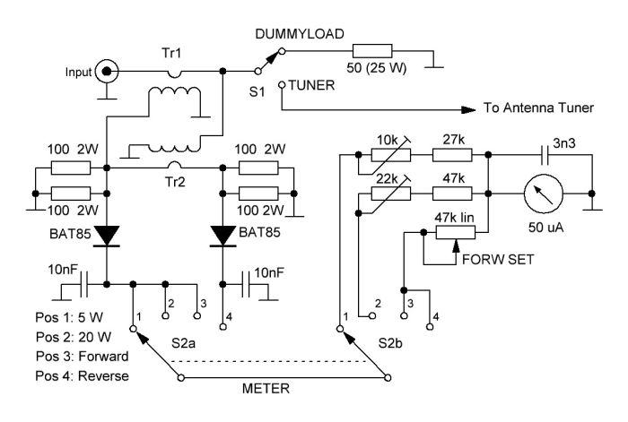 Fig. 4. Stockton Power Meter.
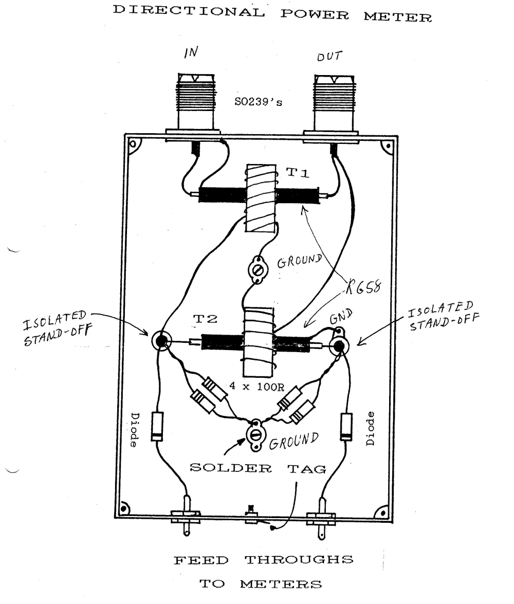
The power
meter is built around two transformers: T1 and T2. Each transformer has one
winding on the primary side and 12 windings on the secondary
side. The single wire (on the primary side) is a piece of RG-58 coax
cable (50 ohm impedance). The secondary side is 12 turns of isolated wire (about 22
AWG) wound on a toroid core (Amidon T-68-6).
The sketch below was enclosed with the kit from Kanga Products. It shows how T1 and T2 are mounted.
 Mounting of T1 and T2. Click the picture to enlarge.
Set
S1 to DUMMYLOAD. Set the METER switch in pos. 1 and apply exactly
5 W at 28 MHz (or lower) to the input terminal. The applied power is
measured with another power meter. Adjust the 10 kohm trimmer to set
the needle at the 5 W mark. The remaining scale is marked with a thin
pen. I have set marks at 4 W, 3 W, 2 W, 1 W, 0.5 W and 0.2 W. This
calibration requires that the output of your power source can be
reduced!
Calibration of 20 W range
Set
S1 to DUMMYLOAD. Set the METER switch in pos. 2 and apply exactly 20 W
at 28 MHz (or lower) to the input terminal. The applied power is
measured with
another power meter. Adjust the 22 kohm trimmer to set the needle at
the 20 W mark. The remaining scale is marked with a thin pen. I have
set marks at 15 W, 10 W, 5 W, 2 W and 1W. This calibration
requires that the output of
your power source can be reduced!
Calibration of SWR meter
Set
S1 to DUMMYLOAD. Set the S2 METER switch in pos. 3 and apply a few
watts of power to the input terminal. Adjust FORW SET to full meter
deflection. Move the S2 METER switch to pos. 4 and read the meter. The
deflection in pos. 4 should be zero (or close to zero) because the
SWR is 1:1 (Input impedance is 50 ohm and the dummyload is 50 ohm).
This is marked as "1" on the meter scale. Now replace the 50 ohm
dummyload with a 100 ohm resistor and repeat the procedure. This is the
"2" mark. Insert a 150 ohm resistor, repeat the procedure, and
mark the "3" deflection on the meter scale. Finally, reconnect the
50 ohm dummyload.
How to measure SWR during operation
Set
S1 to TUNER. Set the S2 METER switch in pos. 3 and apply a few
watts of power to the input terminal. Adjust FORW SET to
full meter deflection. Move the S2 METER switch to pos. 4 and read the
meter. The deflection in pos. 4 shows the SWR. Leaving S1 in position 4
is useful when the antenna tuner is being adjusted. You
can monitor how each twist of a knob affects the SWR.
Balanced Antenna tuner
The tuner's input circuit is unbalanced and it consists of Cin and Lin.
The balanced output circuit consists of Lout and Cout. Lout is
an inductor with
2 x 6 taps. The balanced output terminals can be connected to any
pair of taps (symmetrically)
using the rotary switch S1. As an additional feature, Cout can be
connected to any pair of taps by alligator clips. This
makes tuning at high frequencies easy because the Lout
inductance is less if Cout is connected to one of the inner
taps, e.g. the #3 taps. Cout should always be connected
symmetrically to the Lout taps. Lout is not grounded.
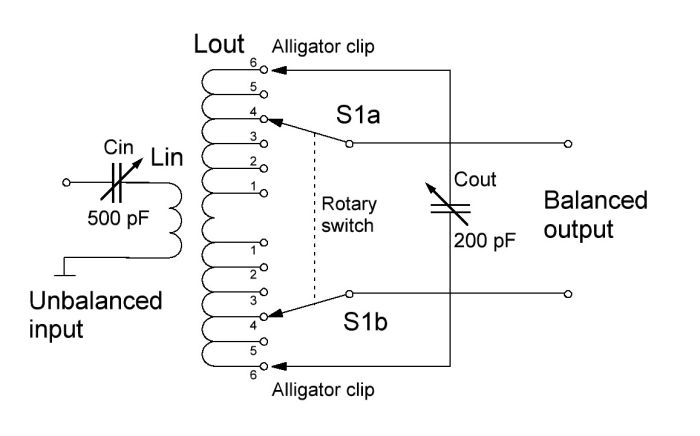
Fig. 5. Balanced Antenna Tuner.
| Component |
Remarks |
| Lin |
5 turns 0.6 mm (22 AWG) on center of Lout |
| Lout |
26 turns 0.6 mm (22 AWG). Length of winding is 28 mm (about 1 inch).
Make 6 taps every 2 turns beginning from one side; then make 6 more taps beginning from the other side. |
| Coil form |
Diameter is 26 mm (1 inch); length is 60 mm (2½ inch).
The coil form is a plastic container used for coins. I asked for one in a local bank and got it for free. |
Antenna examples
This balanced antenna tuner has many applications. I've used it with the
following antenna types:
-
Delta loops for 10, 15, 17, and 20 meters
-
Horizontal loop for 10-40 meters
-
Dipoles for 10 and 20 meters
-
Multiband doublet 10-40 meters
Pictures
Here are more pictures showing the construction of L and its taps.
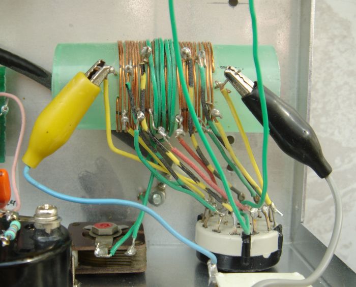
Figure 6. Cout is connected to the two taps #6 (used at low frequencies).
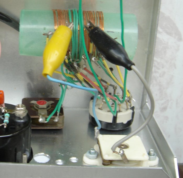
Figure 7. Cout is connected to the two taps #2 (used at high frequencies).
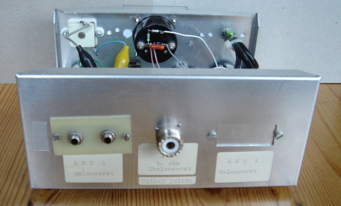
Figure 8. Rear view.
Latest revision November 16th, 2015 by Lars Petersen, OZ1BXM.
OZ1BXM Home