DX FT8 notes

Notes on building the "DX FT8" transceiver from a kit sold by K5BCQ.

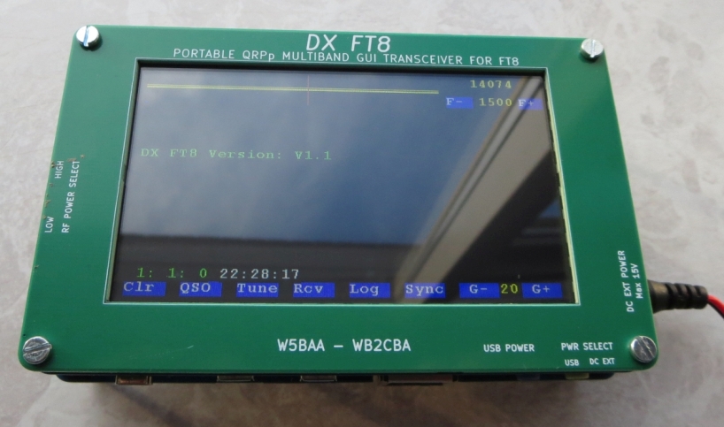
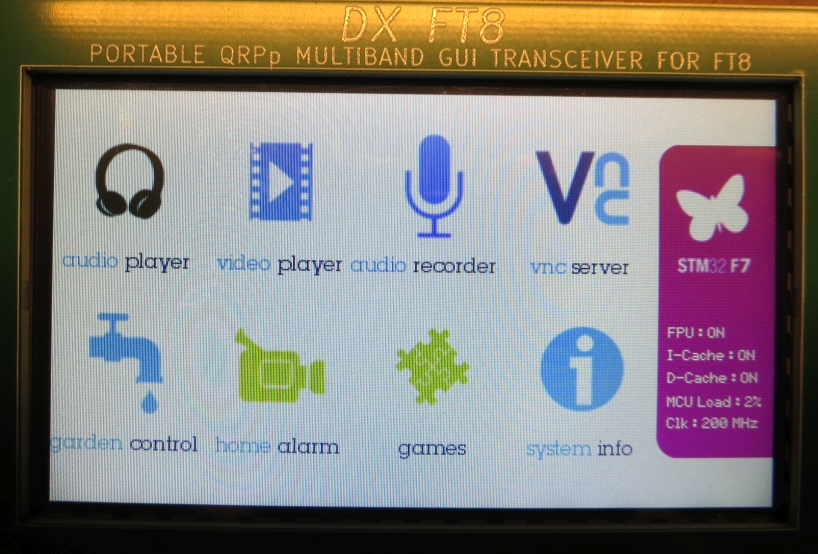
screen of dx ft8
Figure 1. DX FT8 during operation (photo by WB2CBA).


DX FT8 - A QRPp 5 band stand alone FT8 transceiver with touchscreen GUI terminal (video by WB2CBA)

The "DX FT8" project is published as open source on the Github page of WB2CBA.

There are some posts with subject "DX FT8" in the uDX group. A user group dedicated "DX FT8" was formed November 22th, 2024: DXFT8@groups.io | Home

The computer part is a factory assembled Evaluation Board from STMicroelectronics with an integrated 4.3" touch screen. It is called DISCO board on this page. The DISCO board can be purchased from Digikey and other sources.

The radio part is an assembled PCB containing receiver and transmitter. A few leaded components are solder by the user. I ordered the radio part from K5BCQ.
 
The radio part's circuit diagram V1.1 (PDF) is here.

DISCO Board

The DISCO board is STM32F746G-DISCO from STMicroelectronics. The PC utility "STM32 ST-LINK" is downloaded and installed before firmware is loaded into the DISCO board. This is described in the user guide DX_FT8 FT8 DIGITAL MODES HF GUI TRANSCEIVER Programming And User Guide_REV1.3.pdf.

 Below are screen-dumps and pictures I took during installation.

first time pwr up SCREEN
Figure 2. DISCO screen after power up (no firmware loaded).

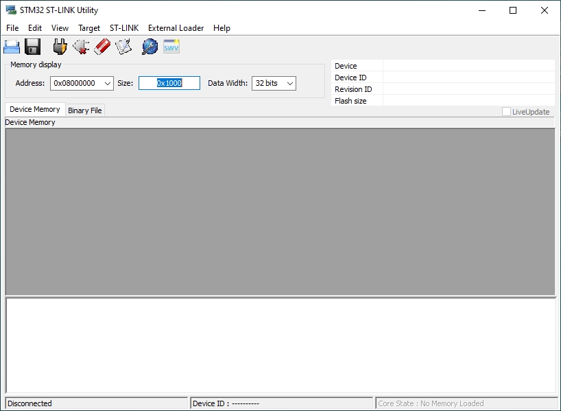
STM32 ST-LINK 1
Figure 3. ST-LINK Utility (not connected).


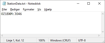
station data
Figure 4. 
StationData.txt is created by Notepad
and saved on the flash card.


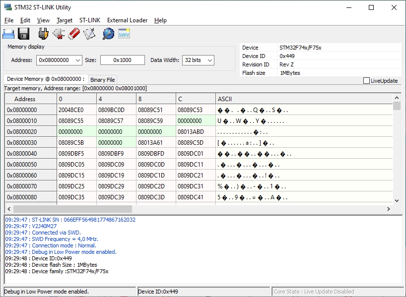
utility connected
Figure 5. ST-LINK connected to the DISCO board via yellow USB port.


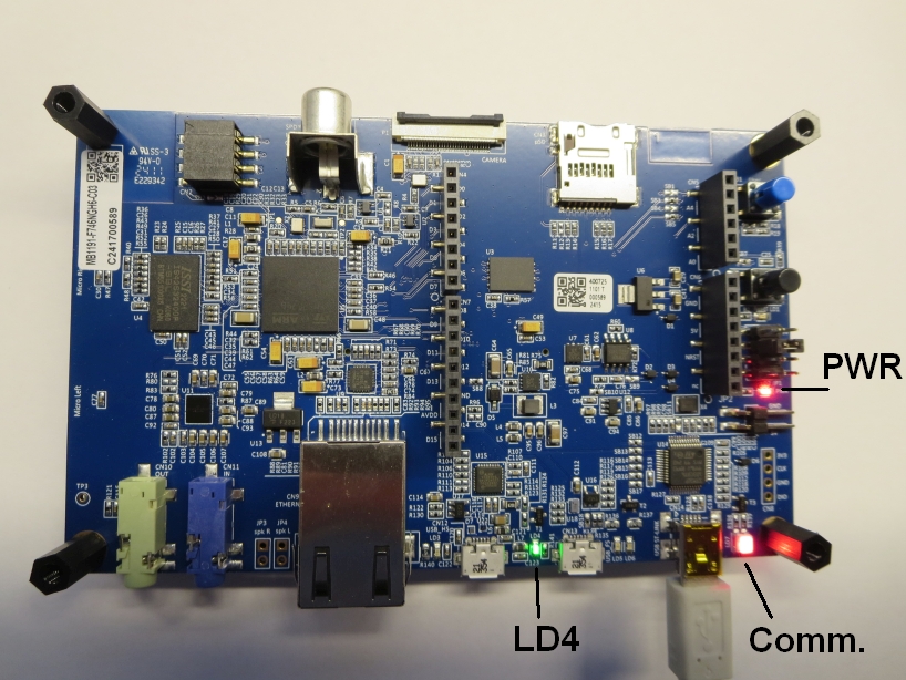
LEDs
Figure 6. 
DISCO connected to the PC utility via USB.
LD4 is flashing. PWR is constant. Comm. is flashing when there is traffic on the USB interface


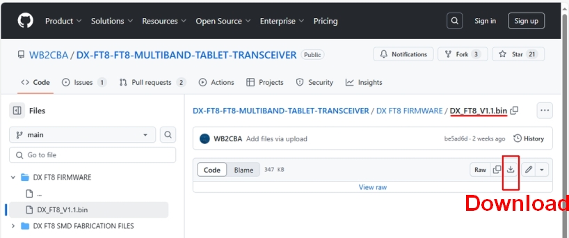
download from github
Figure 7. Download the .bin file from Github by pressing the "Download" icon.

Download the .bin file from Github exactly as shown in figure 7 above.
Do not download via your browser's "Save as" function. The saved file won't work. I speak from experience!

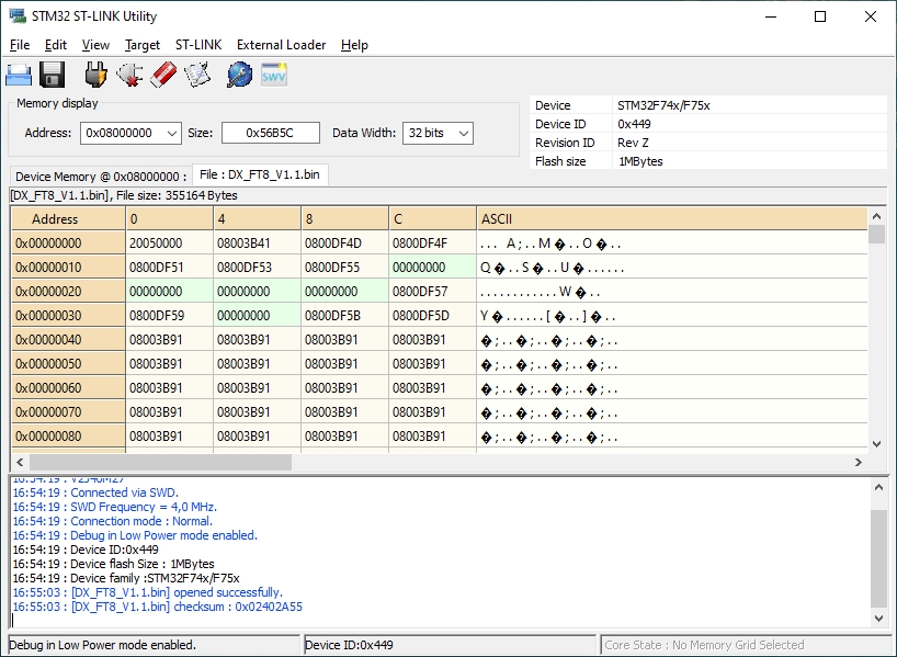
load file
Figure 8. Select "File > Open file" to open the desired file.
Please disregard the questionmarks in the ASCII column (they were caused by an error in my PC).


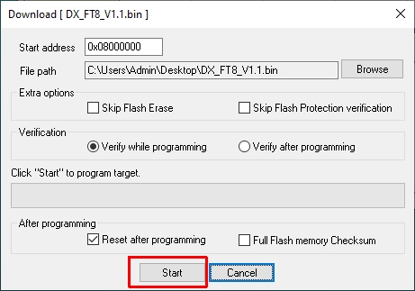
press start
Figure 9. Select "Target > Program"
and press "Start" to download the firmware.


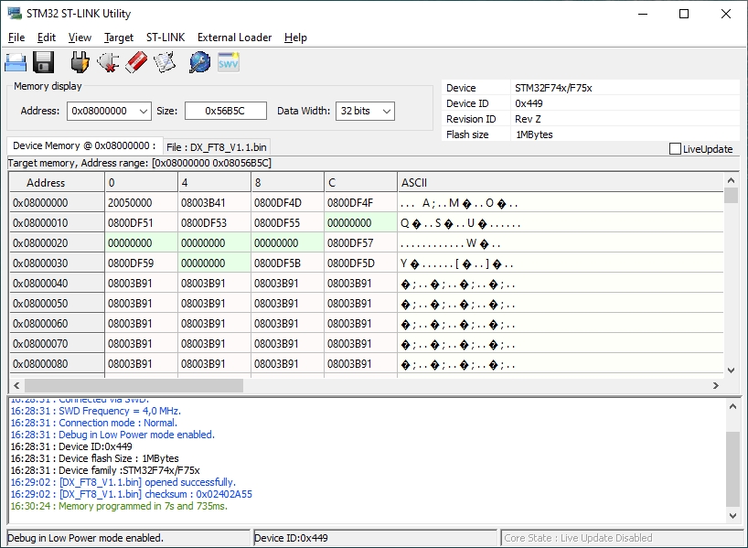
DL finished
Figure 10. Download finished.


DX FT8 runs
Figure 11. DISCO screen after download completed.

RF Board 

The RF board was builty from a kit purchased from K5BCQ. The RF board in the kit is populated, except for a few components Follow the "hardware build guide" to fit remaining components.

I cut off 3 legs (plastic) on the battery holder in order to fit the PCB. The two SPDT slide-switches were mounted vertically - they can be operated using a pen.  

The measurements below were taken after the RF Board was connected to the DISCO board. Multimeter: Fluke 17B+. Oscilloscope: Owon HDS272S (BW 70 MHz) with 10x probe.

testpunkter
Figure 12. RF Board test points.
                                                                                                                                                                                                                                                                                                                                                                                                                                                                                                                                                                                                                                                                                                                                 
Prepare measurements:
Terminate J1 with 50 ohm. PSU 12.0 V DC connected to J3. All measurements refer to Ground (TP4).
SW1 position EXT; SW2 position HIGH

Receive 14.074 MHz
Transmit 14.074 MHz
U12 pin 44.97 V DC4.97 V DC
U5 pin 23.30 V DC3.30 V DC
I from PSU280 mA505 mA
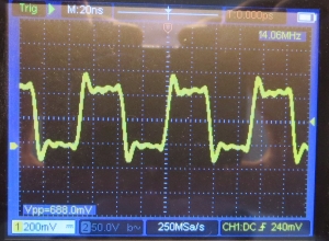
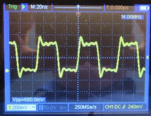
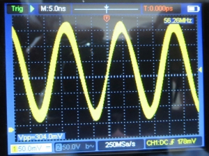
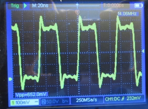
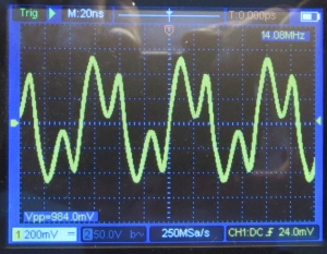
TP1 (I)fig. Afig. D
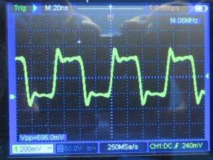
TP2 (Q)fig. Bfig. E
TP3 (CLK0)no signalfig. F
TP5 (V_PA) 4.67 V DC6.58 V DC
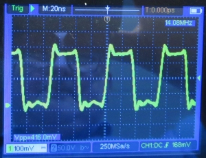
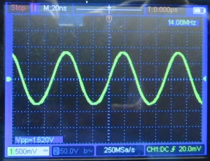
TP6 (CLK1)fig. Cfig. G
TP7 (TR1)no signalfig. H  
Poutno signal812 mW (29.1 dBm)
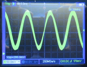
Output waveformno signalfig. I
Figure 13. RF Board measurements.

Click each picture to enlarge
fig Afig Bfig C
fig. Afig. Bfig. C

Click each picture to enlarge
fig Dfig Efig F
fig. Dfig. Efig. F


Click each picture to enlarge
fig Gfig Hfig I
fig. Gfig. Hfig. I (output waveform)


OZ1BXM Lars Petersen oz1bxm@pobox.com. Revised 22-Nov-2024. 

Home