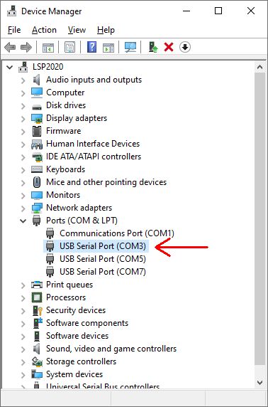
 Figure 2. Device Manager (Windows 10).
I'm using
the DigiMaster IF232 interface from
ZLP-Electronics
for connecting the PC to the transceiver's CAT-port (fig. 3). It
seems like the DigiMaster IF232 is obsolete. A similar unit
may be found at
ZLP-Electronics.
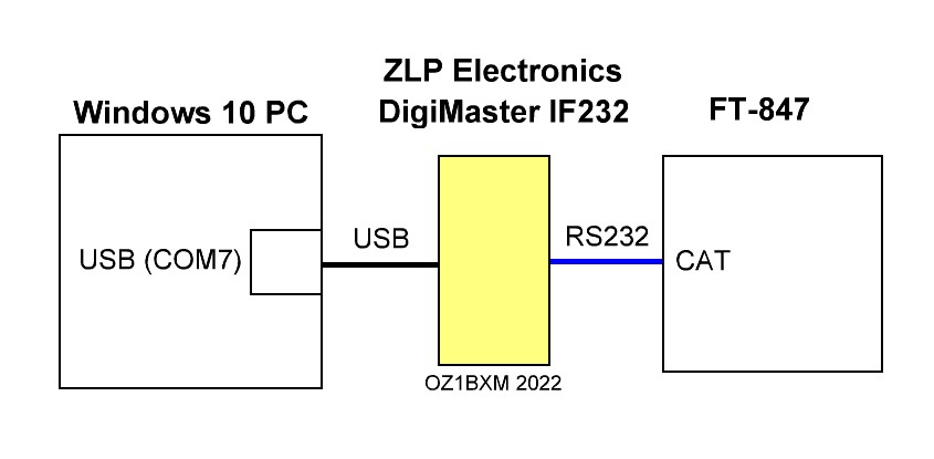
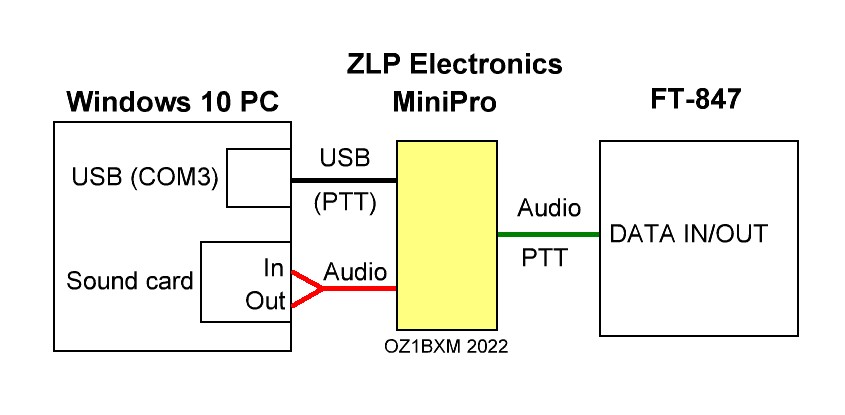
Figure 3. CAT cabling between PC and FT-847.
The
black cable in figure 3 is an USB cable. Once connected,
Windows assigns a serial port
number (COM7 in my case) and associates it with the DigiMaster
IF232. You can view the serial port
number in the Device Manager as shown in fig. 2. The
blue cable is a serial cable connected to the CAT port of
Yaesu FT-847. Both cables were supplied by ZLP-Electronics.
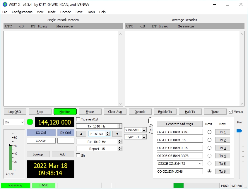
Figure 4. WSJT-X Main window.
The "Sync" value should be set low for best sensitivity.
The
amount of RF power sent to the SSPA from the FT-847 transceiver can be
set using the "Pwr" slider (fig. 4). This slider controls the
amplitude of the AF signal, which modulates the transmitter.
RF power can also be set using the RF PWR knob on the transceiver.
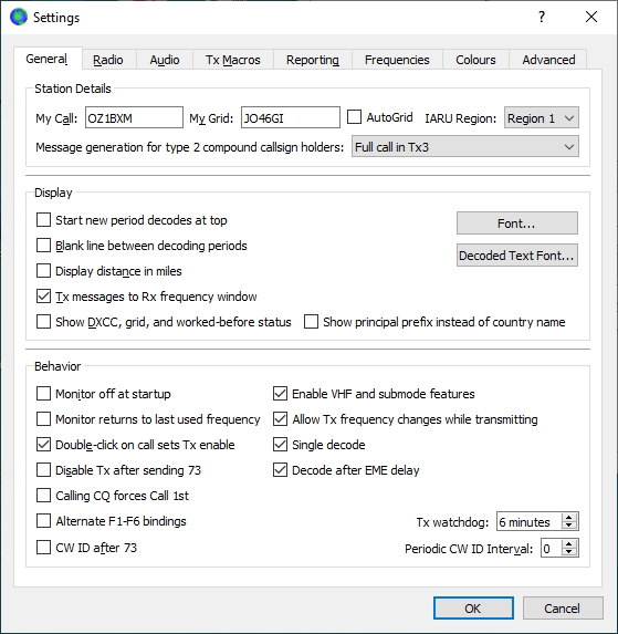
Figure 5. File > Settings; General tab
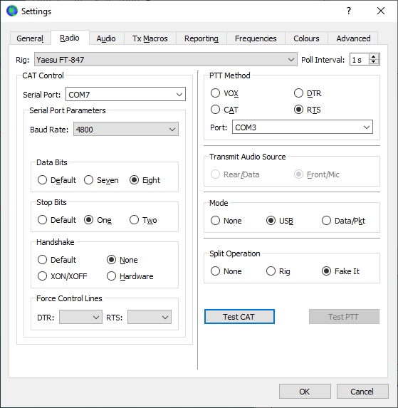
Figure 6. File > Settings; Radio tab
Press
the "Test CAT" button for testing the CAT connection. If successfull,
the "Test CAT" turns green, and the "Test PTT" button is enabled.
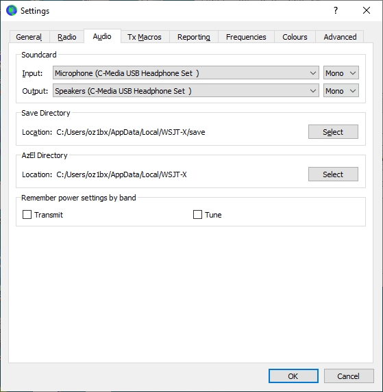
Figure 7. File > Settings; Audio tab
The soundcard in fig. 7 is an external one connected to the PC via USB.
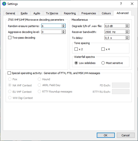
Figure 8. File > Settings; Advanced tab
"Tx
delay" is the time between PTT activation and the
beginning of AF sound transmission. During this time, the
relays, the preamp, and SSPA must change from receive to transmit.