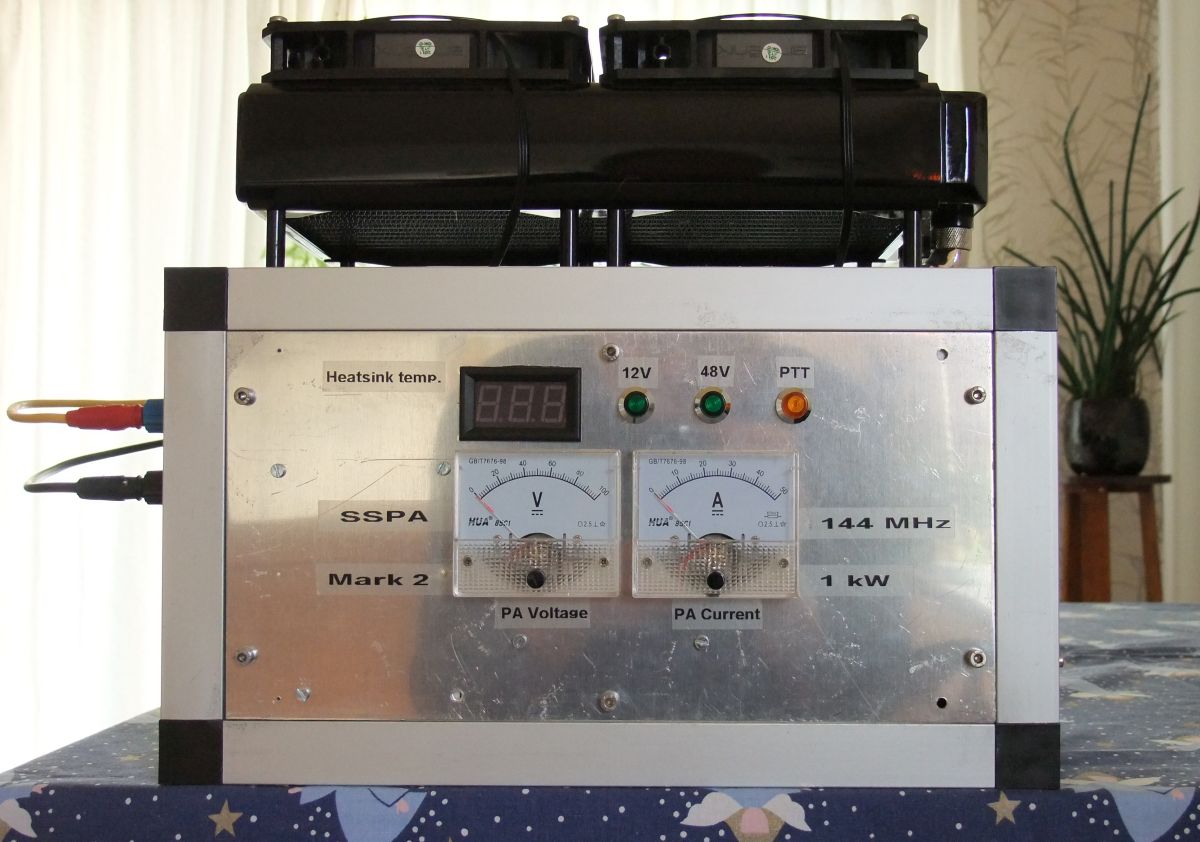
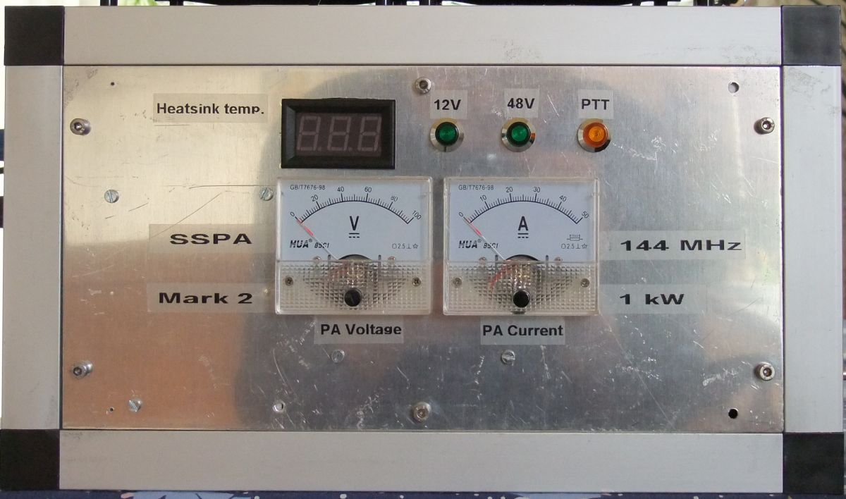
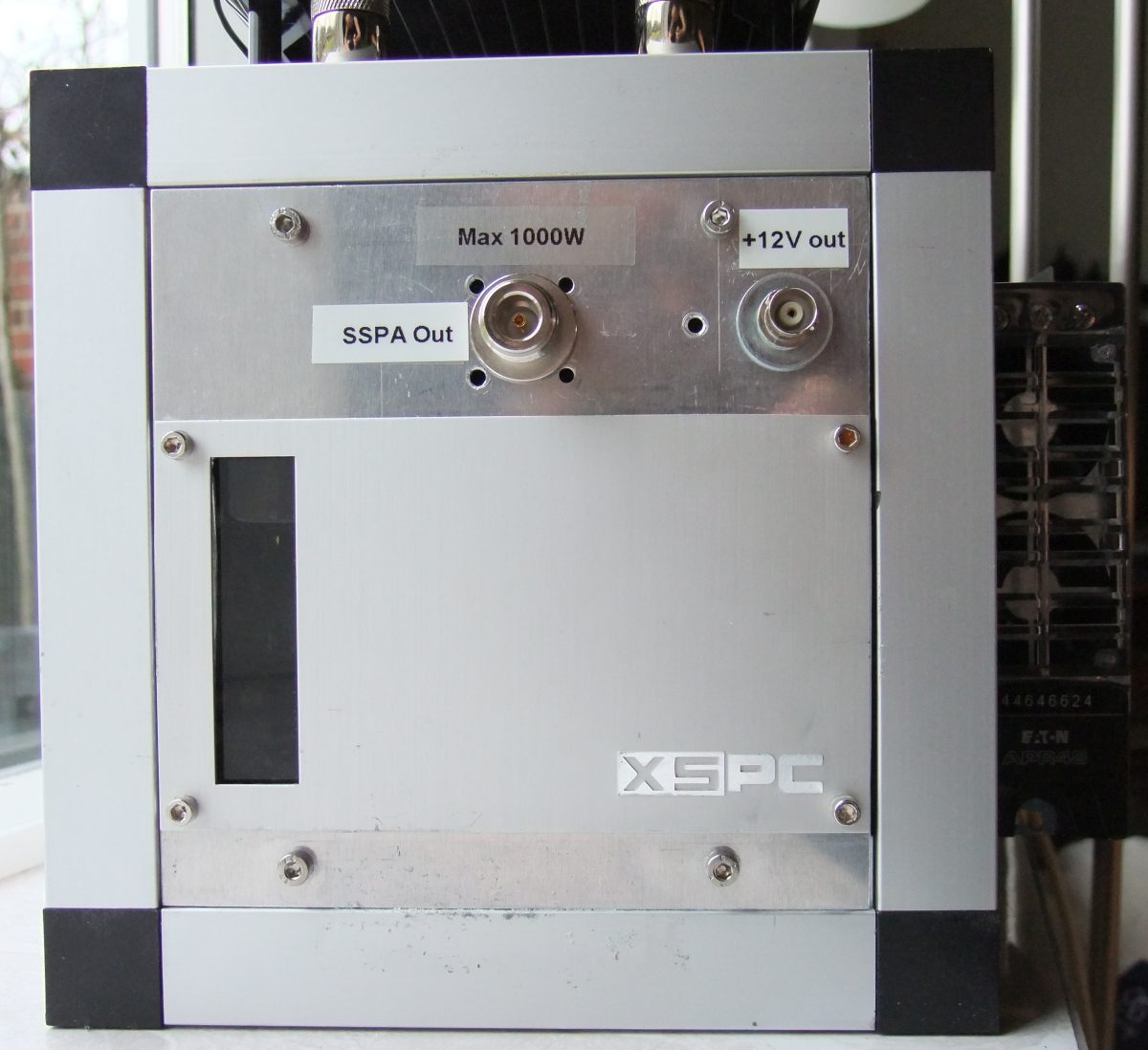
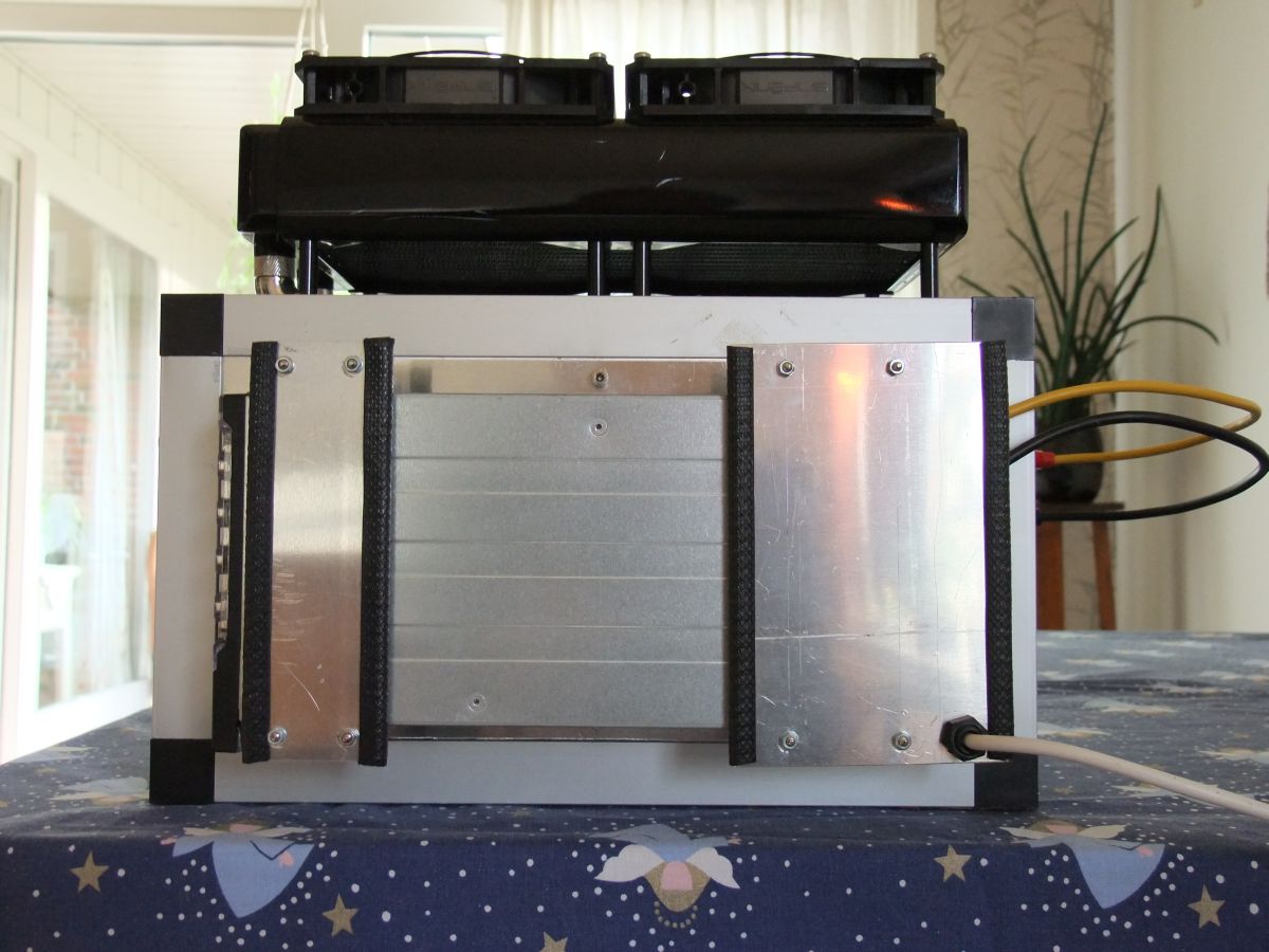
The finished SSPA.
This page describes my homemade Solid State Power Amplifier (SSPA) for 144 MHz. It was made primarily for EME work. The construction is based on DUBUS 4/2010 where Lionel Mongin (F1JRD) describes the concept. Later development was done by several radio amateurs, among them W6PQL James Klitzing.
The finished SSPA.
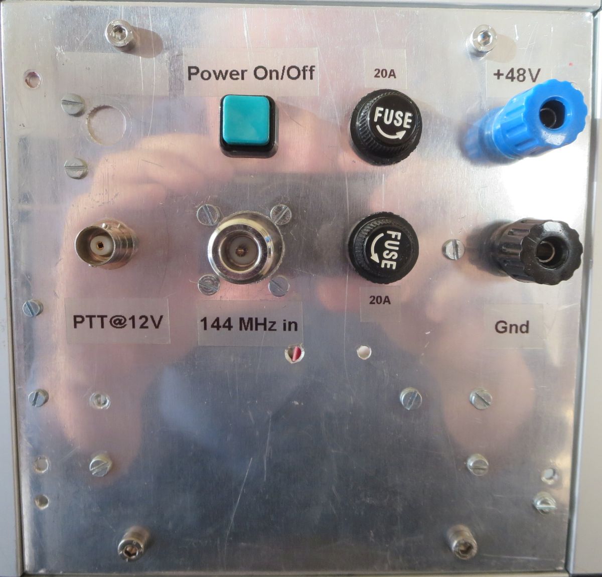
My SSPA design approach is simplicity. On the front, I can read DC voltage and DC current on analog meters. I can read the heatsink temperature, and there are 3 bulbs indicating 12V, 48V, and PTT.
Watercooling was chosen because it separates the transistor from the radiator. The transistor and heatspreader are placed inside the cabinet; the radiator is mounted on top of the cabinet where it is cooled by two large fans. This concept should be more silent than ducted air cooling with high-speed fans. Another reason for choosing water cooling was pure curiousity! I wanted to explore how water cooling actually worked.
W6PQL: Solid State 1 kW Linear Amplifier for 2 Meters (article in QST Oct. 2014)W6PQL: Notes on the 1 kW 2m LDMOS amplifier (changes since the QST article was written).
W6PQL: 2 Meter KW Amplifier Kit Assembly Instructions
Description
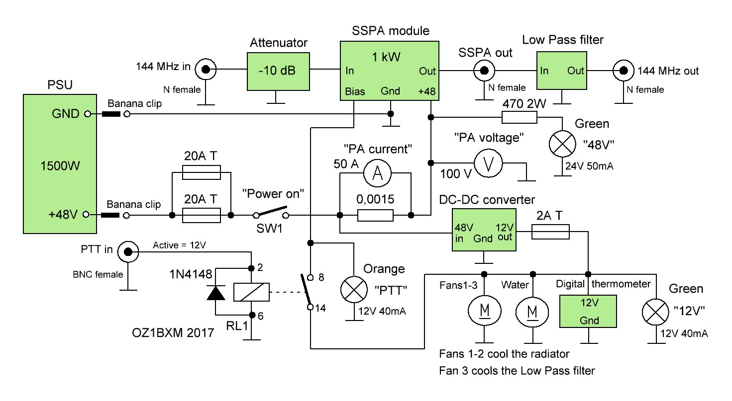
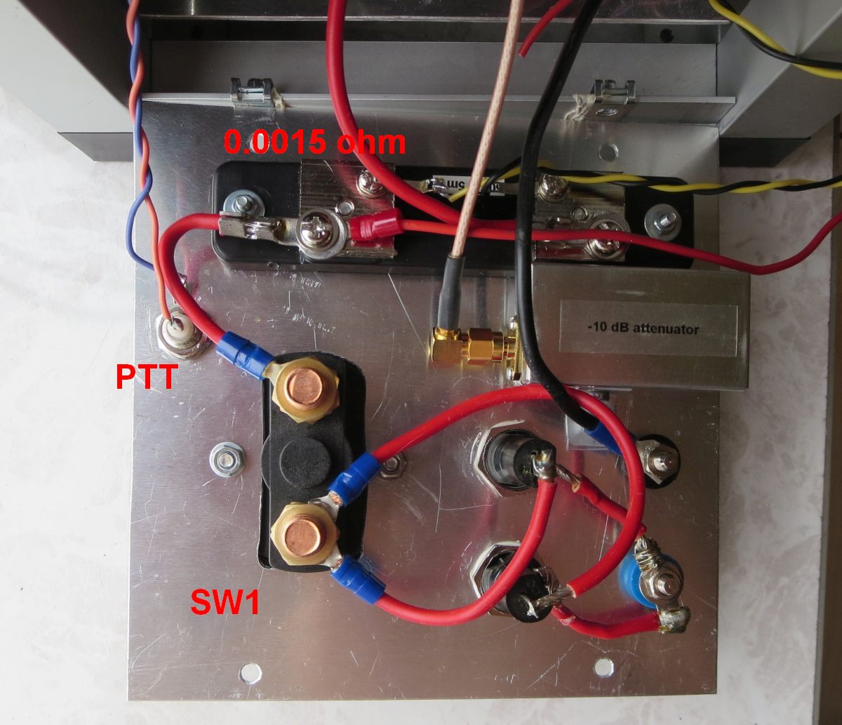
I've modified the SSPA bias circuit slightly as shown below:
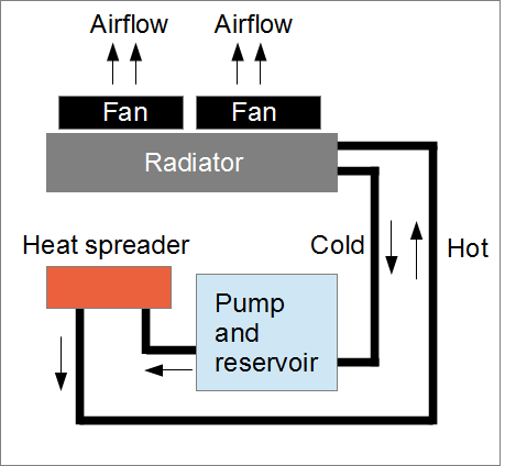
Below is a block diagram showing how the different units are connected in the SSPA:
|
|
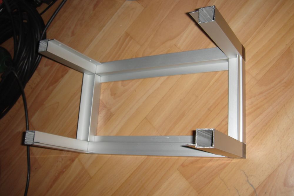
Cabinet assembly, part 1 Cabinet width is 30 cm (inner dimension). Cabinet deepth is 15 cm (inner dimension). Cabinet height is 15 cm (inner dimension). |
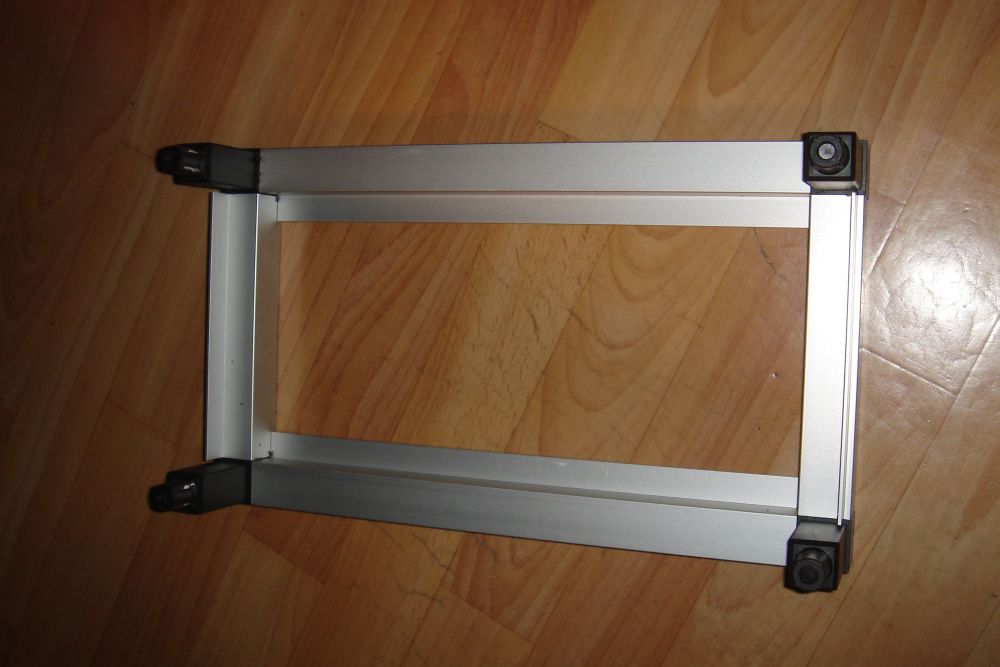 Assembling the cabinet, part 2. |
Cabinet assembly, part 2 The black end-pieces are forced into the alu elements using a hammer. |
|
|
|
 Assembling the cabinet, part 3. |
Cabinet assembly, part 3 The aluminium elements are hollow. |
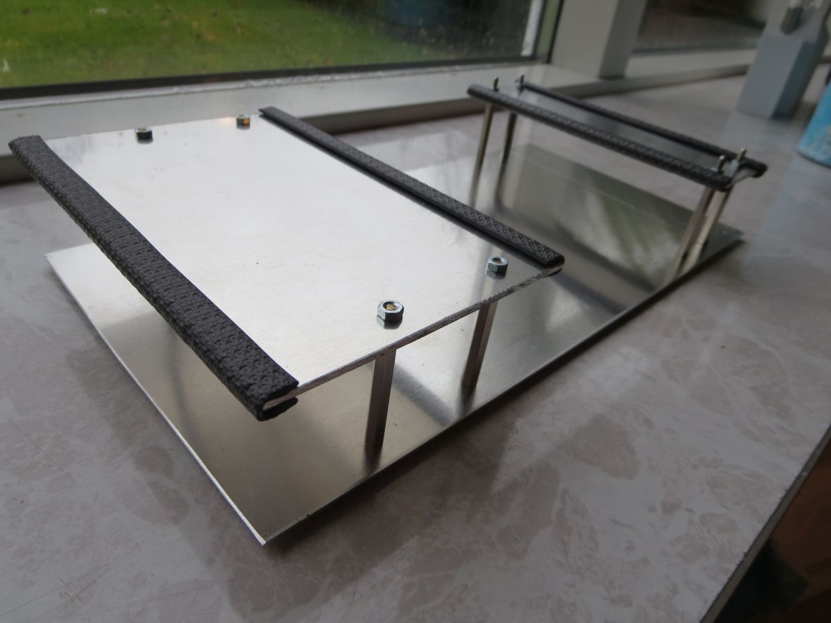
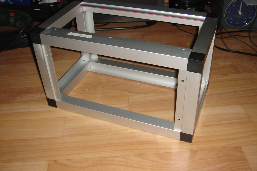 Assembling the cabinet, part 4. | Cabinet assembly, part 4 The aluminium frame is now finished and only the 6 panels remain. Front/rear panel: 30 cm x 15 cm Top/bottom panel: 30 cm x 15 cm Two side panels: 15 cm x 15 cm I bought five 30 cm x 15 cm x 2 mm alu sheets for the side panels. Four of them were used for front/back/top/buttom panels. The remaining sheet was cut in two, each part now measuring 15 cm x 15 cm. These two sheets were used as side panels. |
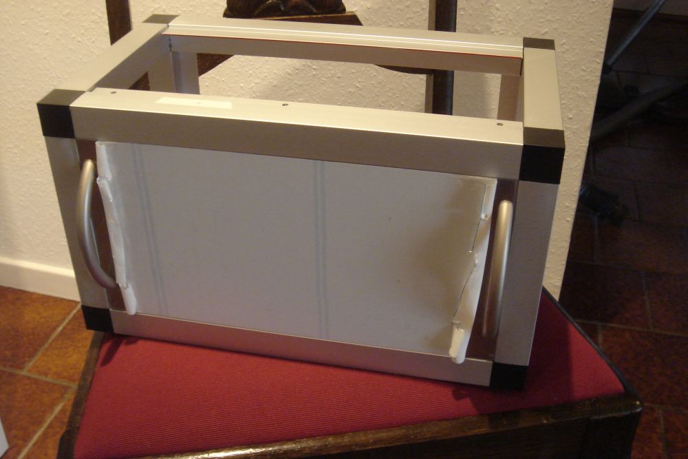 Assembling the cabinet, part 5. | Cabinet assembly, part 5 The front panel is mounted temporarily. |
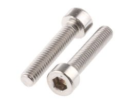 M4x12 bolt. 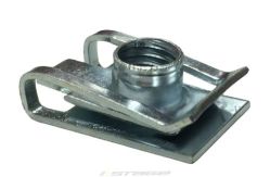 M4 threaded clip. | Mounting the panels The panels are fastened onto the frame using M4x12 bolts and M4 threaded clips (they are sometimes called "chimney U clips"). The bolts can be obtained in any home improvement store. I bought the clips on ebay.com (stagemotorsports). |
|
|
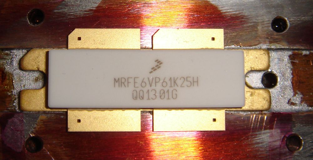
Soldering the LDMOS transistor Soldering tips: Ensure that the transistor flange is parallel to the copper spreader. All parts of the transistor flange must have excellent thermal contact with the heat spreader. I
made an error when I
soldered the LDMOS transistor:
30% of the flange had no thermal contact to the copper spread. The
transistor became overheated when put into service. I
had to resolder the transistor to ensure proper thermal contact. |
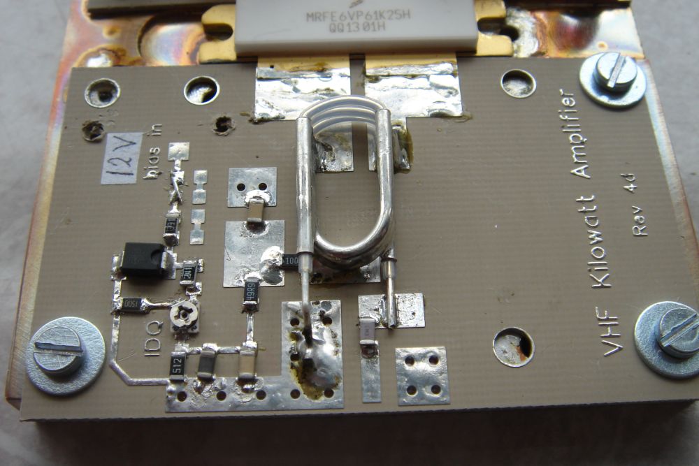 The left PCB is mounted. | Assembly and mounting of the left PCB
There is plenty of space on the left PCB. Soldering the SMD components was not difficult. I have changed the bias circuit slightly. The original circuit diagram by W6PQL is here. My revisions can be found here. Both links will open in a new window. Finally, the LDMOS gate terminals are soldered to the PCB. I used a temperature controlled soldering iron suited for SMD for most of the work. The two LDMOS gate terminals were soldered using a 30 W soldering iron. |
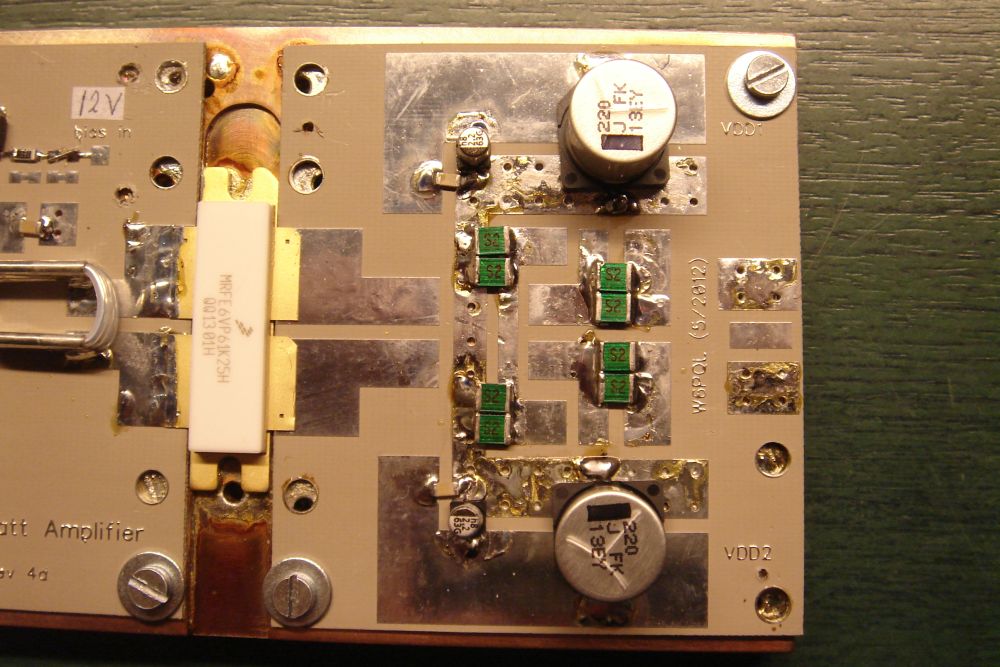 Capacitors are fitted on the right PCB. | Assembly and mounting of the right PCB, part 1
All capacitors, except the two coaxial capacitors, are soldered first. I used a 30 W soldering iron for the bigger components, and an SMD soldering iron for the small parts. |
 Two impedance transformers TC-12 are fitted. | Assembly and mounting of the right PCB, part 2
The two impedance transformers (TC-12) are made of white coax cable. The coax just visible to the right is a 35 pF coax capacitor. The two copper coils are each 200 nH. They carry supply voltage to the transistor. I used a 30 W soldering iron for this task. |
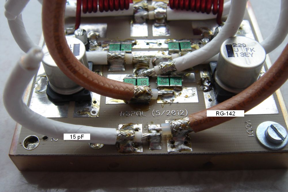 Impedance transformer RG-142 is fitted. | Assembly and mounting of the right PCB, part 3
The impedance transformer RG-142 is made of brown coax cable. The white 15 pF coax capacitor is visible in the foreground. The LDMOS source terminals are eventually soldered to the PCB. I used a 30 W soldering iron for this part. |
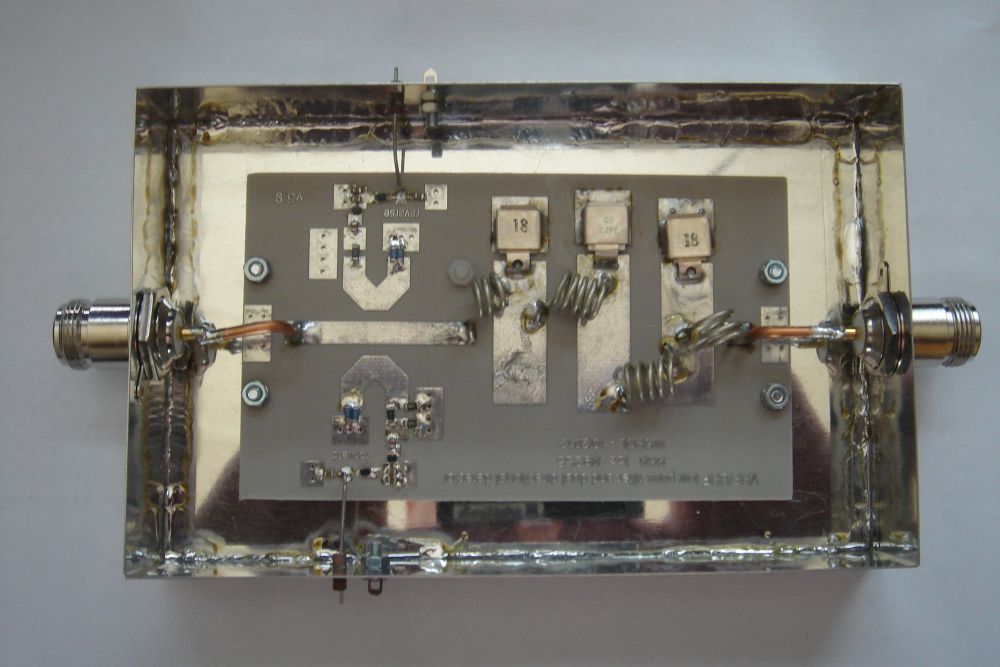
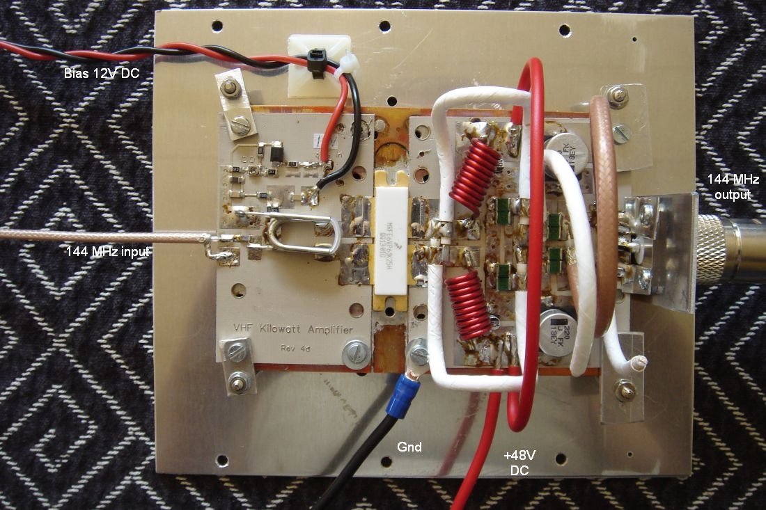 The finished 1 kW pallet for 2 meters. | Finished RF pallet The pallet is mounted onto a 2 mm alu sheet measuring 150 mm x 175 mm. A piece of thin teflon coax connects the RF pallet's input to the N-female ("144 MHz in") on the left side panel. A short piece of RG400 connects the RF pallet's output to the N-female ("144 MHz out") on the right side panel. |
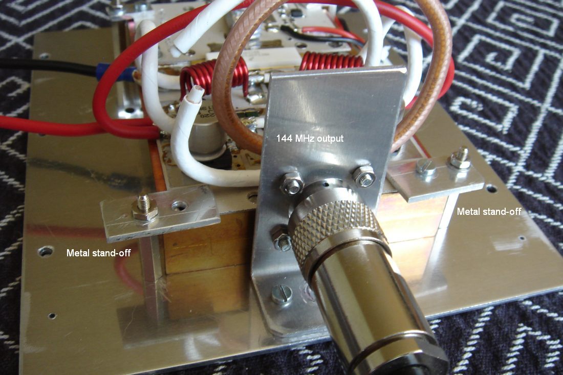 Securing the heat spread. | Attaching the heat spread
The heat spread is attached to the alu sheet by means of four metal stand-offs. |
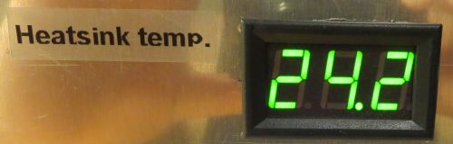 Digital thermometer. | Digital thermometer
The heatspread temperature is measured by a digital thermometer. The temperature range is -55 to +125 oC. Benefits of a LED thermometer:
|
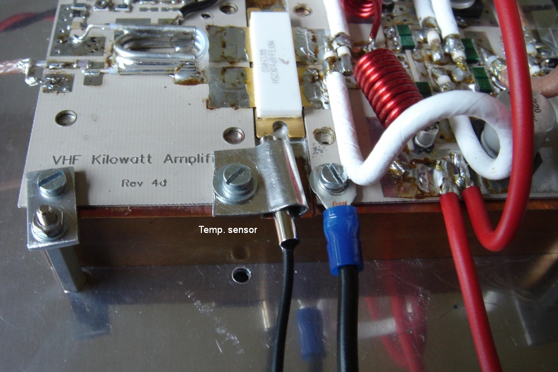 Temperature sensor. | Temperature sensor
The temperatur sensor is attached to the copper heat spread. A piece of tinplate holds the sensor firmly against the heat spread. |
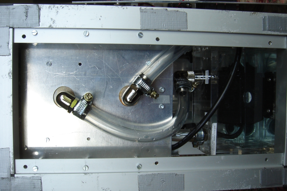 Water tubes connected to the heat spread. | Water tubes connected to the head spread
I've made two holes in the alu sheet of the pallet to allow space for fittings. The water tubes are connected as shown in the picture. The left tube is connected to the water pump's outlet. The right tube is connected to the radiator. |
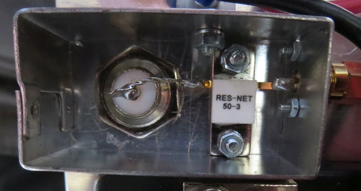 Input attenuator. | Input attenuator
The 3 dB input attenuator can dissipate 50 W. Input/output impedance of the attenuator is 50 ohm. I bought the attenuator at ebay.com (henryradio). The attenuator is mounted on the side panel and enclosed by an alu-box. The input connector is N-female and the output connector is SMA-female. |
| RF input | RF output | Vcc | Ic | Gain | Efficiency |
| 0.4 W | 200 W | 50 V | 12.0 A | 27.0 dB | 33 % |
| 0.7 W | 400 W | 50 V | 16.5 A | 27.6 dB | 48 % |
| 0.95 W | 500 W | 50 V | 19.5 A | 27.2 dB | 51 % |
| 1.3 W | 600 W | 50 V | 21.5 A | 26.6 dB | 56 % |
| 1.6 W | 700 W | 50 V | 24.0 A | 26.4 dB | 58 % |
| 2.0 W | 800 W | 50 V | 26.0 A | 26.0 dB | 61 % |
| 2.5 W | 900 W | 50 V | 28.0 A | 25.5 dB | 64 % |
| 3.5 W | 1000 W | 50 V | 30.0 A | 24.5 dB | 67 % |
|
|
Low Pass filter |
 The filter is enclosed in a tinplated box. | Filter shield The Low Pass filter is enclosed in a RF-tight tinplated box (without lid). The two thick copper-wires are short pieces of Aircom Plus center conductor. |
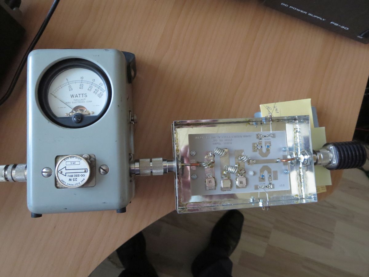 Measuring SWR on the Low Pass filter's input. | Adjusting the filter SWR is measured on the filter's input, and the filter should be adjusted for the lowest value. I used 25 W on 144.150 MHz as test signal, and a Bird 43 wattmeter with slug 25C (100-250 MHz, 25W). The dummy load was able to consume 25 W in the range 0 Hz to 4 GHz. SWR on the filter's input was measured as 1:1. This is an excellent value, and no adjustment was necessary. SWR on the filter's output was also measured as 1:1. Perfect value! |
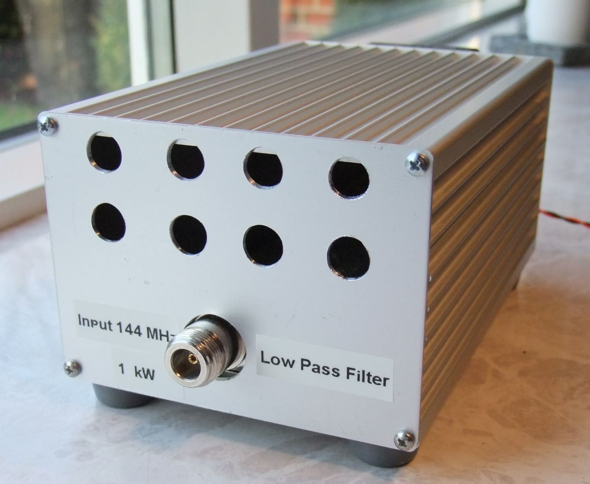 Low Pass filter housed in alu-cabinet with forced air cooling. | Filter cabinet In the beginning I wanted to fit the low-pass filter inside the SSPA cabinet. But sufficient space was not available (the water pump occupies a lot of space). So I've decided to house the low-pass filter in a separate cabinet from Conrad Electronics (item 522953). W6PQL recommends adding a fan if the low-pass filter is used at power levels higher than 500 W. I've added a small fan as I intend to run 1000 W through the filter. The fan is sitting on the rear panel and blows cold air into the cabinet. Warm air is exhausted through 8 holes on the front panel. Fan data Sunon, 50 mm x 50 mm x 10 mm, MB50101V2-000U-A99 4300 RPM, 11 CFM, 26 dB(A), 12V DC, 105 mA |
|
|
Water cooling components The picture shows how the water cooling components are connected. The radiator and the fans are on the top of the cabinet. Pump, reservoir, and the heat spreader are inside the cabinet. Fan data Radiator: HW Labs Black Ice GTX 280 Water pump and reservoir: XSPC X20 750 dual bay Reservoir Pump, rev. 2 Heat spreader: Custom made by PE1RKI, Bert Modderman. Tubing: MasterKleer 15.9/11.1 mm PVC Fittings: EK - ¼" BSPP (G1/4) - ½" (12mm) - High Flow All water cooling components were purchased at Coolerkit.dk | ||||||||||
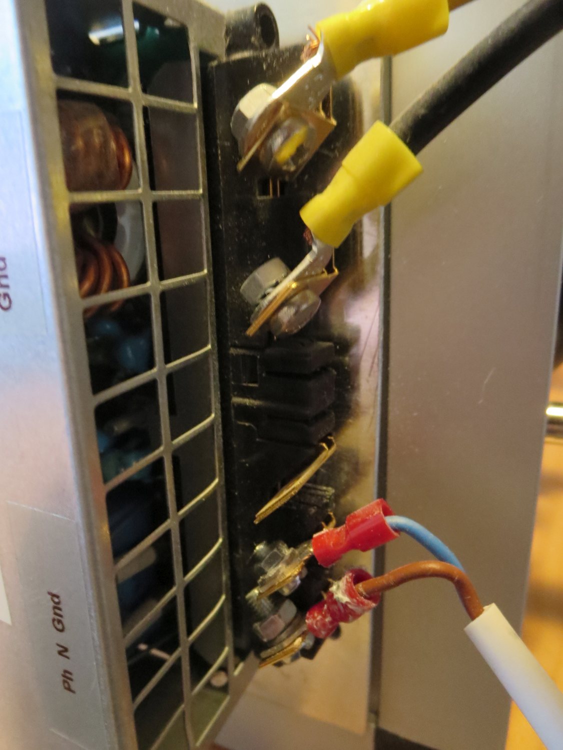
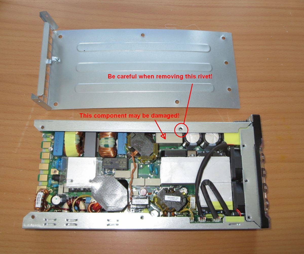 Removing the upper lid (Eaton APR48-3G). | PSU: Open the cabinet The Eaton APR48-3G cabinet must be opened before the mod can be done. The metal cabinet was assembled at the factory using rivets. They are drilled and removed with a 2.5 mm or 3.0 mm drill. Special care must be taken with one of the rivets (see photo). If the drill goes too deep, a component near the hole can be damaged. | ||||||||||
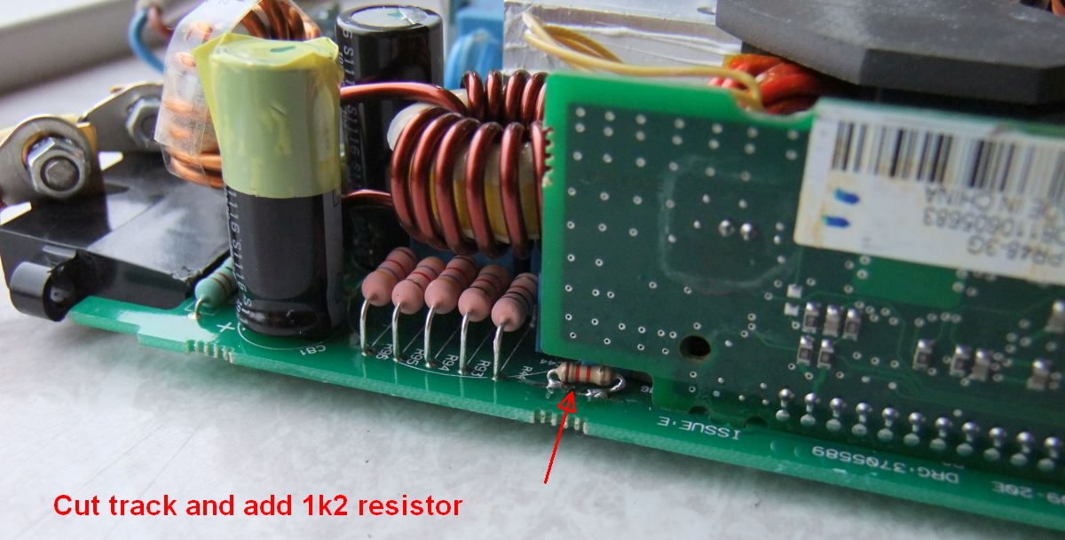 Cut the track and add the resistor (Eaton APR48-3G). | PSU: Increase output to 50.4 V PSU output is factory set to 48 V DC. We need 50 V DC for the MRFE6VP61K25H. A resistor was added to increase the output voltage. Cut the track and solder the resistor as shown in the photo. I tried several resistor values and my final choise was 1200 ohm.
Adding a resistor in order to increase the output voltage was not my own idea. It was described by Allex in Endless Sphere Technology. | ||||||||||
| Item | EUR | DKK |
| Water cooling components | 333 | 2500 |
| Copper heat spread | 160 | 1200 |
| 1 kW pallet kit, low-pass filter kit, filter cabinet, attenuator | 227 | 1700 |
| LDMOS Freescale MRFE6VP61K25H | 240 | 1800 |
| Cabinet frame and panels, analog meters, 70 A relay, lamps, digital thermometer | 174 | 1300 |
| Coax cables, connectors | 67 | 500 |
| Eaton APR48-3G telecom grade PSU (48V DC, 30A, 1500 W) | 400 | *3000 |
| Misc. | 134 | 1000 |
| Total cost | 1,735 | 13,000 |


