Figure 1. Function of the Doppler Tuning Box
I'm using a mobile UHF all-mode transceiver Kenwood TM-455 for satellite downlink. This radio has no RS232 interface. But there is an alternative: The frequency can be changed by keying in the new frequency via a DTMF-enabled microphone like the MC-45DM. In order to do this, the operator must push the PF key first to activate the ENTER function.
This the design idea: Create a doppler tuning box, which receives frequency data via RS232 from the PC, activates the radio's PF key, and enters the new frequency data using DTMF tones. This is shown in the figure below.
Figure 1. Function of the Doppler Tuning Box
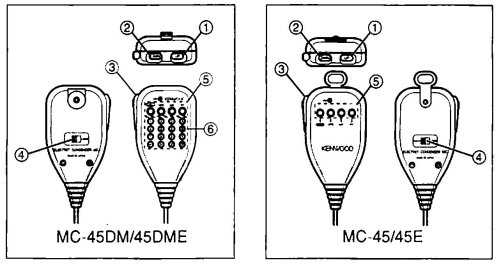
Figure 2. Kenwood microphones.
Item 5 is the PF key, item 6 is the DTMF keypad
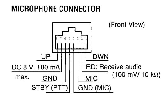
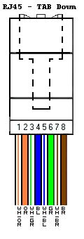
The Kenwood TM-455 microphone connector is a RJ45 type. The connections
are shown in the figure below together with the color codes of a Cat5e
cable.
 |
 |
The function of the microphone keys can be found in the schematic diagram
of the Kenwood MC-45DM microphone (available at www.mods.dk):
|
|
||
|
|
|
|
|
|
|
|
|
|
|
|
|
|
|
|
As seen in the table, the PF key is activated by connecting 100 kohm between pin 1 and 6. The PF key on the Kenwood microphone has no fixed function; it can be assigned and changed by the operator. The default function is Menu access. In this project, the PF key is assigned to ENTER (menu 70, function 84), which means that when activated, the radio awaits 5 digits to be keyed in via a DTMF microphone. The digits can for example be 73210 meaning that 437.321.0 MHz is entered. The resolution is 100 Hz, and this number is usable for satellite doppler correction.
Software
Figure 4. Software flowchart.
The software is written in PBASIC, a BASIC dialect used for programming the Basic stamp family. Free development software is available at www.parallax.com. As PBASIC contains many useful commands, the software has been easy to write and the source code is quite compact. Only 12% of the 2 Kbyte EEPROM memory in the BS2 stamp is used.
The main blocks in the software are explained in the following.
Initialize and flash LEDs
Variables are initialized and the LED pins and the PF pin are set up
for direction (output) and level. Both LEDs are flashed once. The red LED
is flashed using
GOSUB FlashRedLED which calls this subroutine:
FlashRedLED:
RedLED = IsOn
PAUSE 150
RedLED = IsOff
PAUSE 100
RETURN
The PAUSE command makes a delay (milliseconds). The RETURN command makes the stamp leave the subroutine and jump back to the main loop. There is a similar GOSUB FlashGreenLED command for flashing the green LED.
Fetch CI-V command from RS232 interface
For this project, I'm using Icom's CI-V protocol. CI-V means Computer
Interface version 5. This protocol is supported by most satellite tracking
software, and documentation is available on the Internet. A complete description
of the CI-V command set is available at The
ICOM CI-V Interface by Ekki Plicht, DF4OR.
General CI-V command structure:
| FE | FE | to-adr | fm-adr | cmd | sub | data | FD |
All numbers are in hexadecimal.
FE is the preamble (1 byte); it is sent twice.
to-adr is the address of the device to which this frame is sent (1
byte).
fr-adr is the address of the sender of this frame (1 byte).
cmd is the command (1 byte).
sub is an optional sub-command (1 byte).
data is a field between 0 and 56 bytes long.
FD is the postamble (1 byte).
Most CI-V commands yields a response, for example the requested data, or simply a good/no good response from the rig.
Good response:
| FE | FE | to-adr | fm-adr | FB | FD |
No-good response:
| FE | FE | to-adr | fm-adr | FA | FD |
The PBASIC command SERIN is used for detecting and storing data in the CI-V frame:
SERIN 16, 16780, [WAIT($FE,$FE), SKIP 2, STR civArray\6\$FD]
16 means that the SERIN pin is used for RS232 reception. 16780 means 2400 baud 8-N-1 inverted. WAIT $FE,$ FE makes the command wait until two consecutive FE are detected. SKIP 2 means, that the following 2 bytes are skipped. STR stores the next 6 bytes in an array (civArray). \$FD means, that a byte containing FD will end filling data into the array. This last feature is useful if Good/No-good frames are present. Please note, that only the command byte and the 5-byte frequency data are stored. This implies, that any to-adr and fm-adr can be used since none of them are detected.
Write-to-rig command?
The stamp will test the received CI-V frame to decide, whether it contains
the command Write-to-rig (05) or not. If yes, the stamp will continue.
If no, the stamp discards the frame, flashes the Error LED, and goes back
to fetch a new frame.
Here follows an example of a CI-V frame containing frequency data for the 70 cm band:
Write-to-rig command with frequency data:
| FE | FE | 14 | E0 | 05 | 15 83 29 35 04 | FD |
There is no sub byte. The to-adr is 14 and the fm-adr is E0. The cmd byte is 05 (Write-to-rig). The frame contains frequency data (5 bytes) intended for the rig. Frequency data are BCD-digits (one byte contains 2 BCD-digits). The data field is composed like this:
Data field:
| 10 Hz | 1 Hz | 1 kHz | 100 Hz | 100 kHz | 10 kHz | 10 MHz | 1 MHz | 1 GHz | 100 MHz |
|
|
|
|
|
|
|
|
|
|
|
The data field contains this frequency: 0435.298.315
New frequency?
If the received frame contains new 100 Hz, 1 kHz, 10 kHz or 100 kHz
digits, the basic stamp will activate PF and send DTMF tones. If none of
the four digits have changed, it will return to the main loop. The decision
is taken using IF-THEN and comparing the new frequency with the current
frequency:
IF (current_freq = new_freq) THEN Main 'Return to Main if no change
Activate PF and send DTMF tones
The PF key is activated by GOSUB PressPF which calls a subroutine
and sets PF high for 90 ms and low for 10 ms, before returning to the main
loop:
PressPF:
HIGH PF
PAUSE 90
LOW PF
PAUSE 10
RETURN
Sending DTMF tones is done using the command GOSUB SendDTMF.The tones are send out on P14, the Spkr pin. The subroutine reads the value in bcdhi and generates a DTMF tone (dual tone) for 50 ms. This short time is enough for the TM-455 to detect the digit.
SendDTMF:
DTMFOUT Spkr, 50, 50, [bcdhi] ' Send DTMF tones, 50
ms on, 50 ms off
RETURN
The conversion of frequency data contained in the CI-V command is not covered in this text, please refer to the source code.
An automatic test function is available: By setting P6 high, the stamp will generate a test frequency every 2 seconds. In this way one can test the DTMF interface without setting up a working connection to the satellite tracking software via RS232. Please see the source code for details.
Circuit diagram
Figure 5. Circuit diagram
A Basic Stamp 2 (BS2-IC) is used for the project, but any stamp in the BS2-family can be used. Serial communikation with the PC is done via the DB9 female connector. The connection to the PC is via an ordinary straight-through serial cable.
Basic pins
Pin 24 (Vin) is the power supply pin and it accepts between 6 and 15
V DC
Pin 23 (Vss) is ground. It is connnected to pin 4 (Vss) internally
in the stamp.
Pin 22 is the reset pin. Connect this pin momentarily to ground to
reset the stamp.
Pin 21 (Vdd) outputs +5 V DC stabilized voltage (used for the LEDs).
Pin 1, 2, 3, and 4 are used for RS232 communication (2400 baud 8-N-1).
Testpins
Pin 11 (P6, active high) is the testfreq_pin. When connected to ground,
the stamp runs as usual. If connected to +5V, the stamp will generate press
PF and transmit 5 DTMF-tones on P14 (pin 19) every two seconds.
This test function can be used for checking the connection to the MIC connector
on the radio. No RS232 input is needed for this testprocedure to run.
Pin 12 (P7) is the debug_pin. When connected to +5V, the two LEDs are enabled. Both LEDs are disabled when this pin is a ground level.
LED indicators
The "OK" indicator is a green LED connected to P8 (pin 13, active low).
It indicates that DTMF-tones have been transmitted on P14. This LED is
useful when the stamp is connected to the PC and listens for frequency
data on the RS232 interface. A flash from the LED indicates, that data
in the correct format was received and processed by the stamp. It will
also flash, if the testfreq_pin (P6) is active and frequency data are being
generated internally.
The "Error" indicator is red LED connected to P9 (pin 14, active low). It will flash if a frame with header FE FE is received via RS232 but the frame contains a wrong command-byte. This LED is useful when checking the frame format and the command byte. If received frames makes the LED flash, the preamble in the frame is okay (FE FE), but the command-byte is either missing or wrong (must be 05). The "Error" LED will never flash if the testfreq_pin (P6) is active, because the frequency data generated internally in the stamp are error free.
Both the "OK" LED and the "Error" LED will flash once immediately after a stamp reset.
DTMF and PF
DTMF tones are transmitted on P14 (pin 19). The lowpass filter (1K,
1K, 100 nF, 10 nF) cleans up the waveform. The signal level is then attenuated
by the 47 K resistor and the 10 K trimpot. The trimpot is used for setting
the signal level at the microphone's input terminal.
PF key activation is done by forcing BS170 into conduction by setting P15 (pin 20) high and thereby connecting 100 kohm between pin 6 and pin 1 of the microphone connector. When the basic stamp is reset, all pins are default input. Much to my surprise, I measured 2.2 V DC on a basic stamp input pin (I used a Fluke 75 digital voltmeter with 10 Mohm input impedance). To avoid voltage on the pin, the 100 kohm resistor at the gate of BS170 ties P15 to ground. This keeps P15 at ground level until the stamp software has set the pin direction to output and the pin level to low. Briefly said, the 100 kohm resistor prevents a premature PF key pressure.
Construction
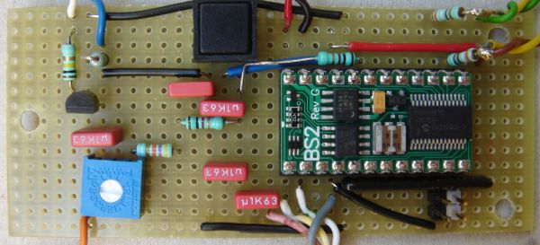
Construction is done using a stripboard with predrilled
holes and using a socket for the basic stamp, see figure 6. The stripboard
I've used measures 40 x 60 mm (1½ inch x 2½ inch). The square
black component is a reset button. The blue component is the 10 kohm trimpot.
The RS232 connector is a DB9 female type. The Cat5e cable going to the
MIC connector is 20 cm (8 inch) long. Connect the Cat5e cable to
the circuit board as shown in the table below.
| Function | Mic | Cat5e cable |
| Dwn | pin 1 | White/orange |
| Mic in | pin 3 | White/green |
| Gnd (mic) | pin 4 | Blue |
| Gnd | pin 6 | Green |
| +8V | pin 7 | White/brown |
Fit the circuit board into a suitable metal box. I've mounted the two LEDs on the front of the box (see figure 7). The blue cable is the Cat5e connecting to the microphone socket of the Kenwood TM-455E. The DB9 connector is mounted on the rear.
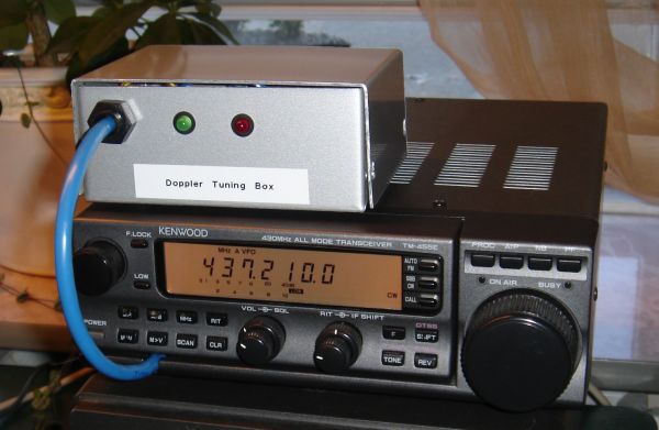
Figure 7. The doppler tuning box on top of the radio.
Programming the PF key
Kenwood TM-455 needs a key press before it accepts frequency input
(that is DTMF tones). The PF key does not have a fixed function; it must
be programmed by setting menu no. 70 to activate function 84 (ENTER). Function
84: "Used with the DTMF mic keypad for direct entry of the operating frequency
or memory channel". See Kenwood TM-455 Instruction
Manual p. 14 and 35-36.
Test 1
The purpose is to test the LEDs and verify generation of DTMF tones.
| Pin | Level | Function |
| P6 | 5V | Generate internal test frequency |
| P7 | 5V | Enable LEDs |
Set P6 and P7 high by connecting them to +5V via 10K resistors. Power up the circuit board using an ordinary power supply. Press the reset button and check, that both LEDs flash once immediately after reset. The green LED will now start flashing every 2 seconds indicating DTMF transmission. Verify the generation of DTMF tones by connecting an amplifier to 'MIC in' and turning up the 10K trimpot. Optionally, you can connect a loudspeaker between ground and P14 with a a 22 ohm resistor in series.
Test 2
The purpose is to connect the Doppler Tuning Box to the radio's MIC
connector, adjust the DTMF level, and verify that the Doppler Tuning Box
controls the radio frequency.
| Pin | Level | Function |
| P6 | 5V | Generate internal test frequency |
| P7 | 5V | Enable LEDs |
Set the 10 K trimpot to minimum output. Turn off the radio, remove the microphone, and connect the doppler tuning box to the radio's MIC connector. Power up the radio and check the voltage on basic stamp pin 21 (Vdd). It should be close to 5 V (I measured 5.0 V). Check also the voltage on Vin pin 24 (I measured 7.2 V). Now advance the 10 K trimpot to increase the DTMF tone level until the radio display changes frequency every 2 seconds.
Test 3
The purpose is to connect the Doppler Tuning Box to the PC and verify
that the satellite tracking software controls the radio frequency.
| Pin | Level | Function |
| P6 | 0V | No test frequency generated |
| P7 | 5V | Enable LEDs |
I'm using Orbitron (cardware) and WispDDE (freeware) for satellite tracking.
Open WispDDE and configure Settings | DDE Link like in figure 8:
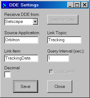
Figure 8. WispDDE settings.
Now configure Settings | Radio in WispDDE like shown in figure 9 below. The CI-V protocol is enabled by selecting an ICOM radio (IC-475). The address of the radio is not important, since the doppler tuning box does not use that information. I have chosen 14 (hex), which is the factory default address of the IC-475. The baud rate is set to 2400.
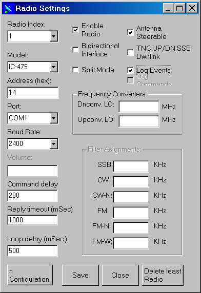
Figure 9. WispDDE Radio settings.
Start Orbitron and choose the tab "Rotor/Radio". In the Driver drop-down box, choose the WispDDE option and click the icon to the right. The sentence "DDE conversation with driver is active" should now be displayed as seen in figure 10.
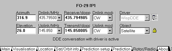
Figure 10. Orbitron screendump: DDE conversation is active.
Check in WispDDE, that the downlink frequency follows Orbitron:
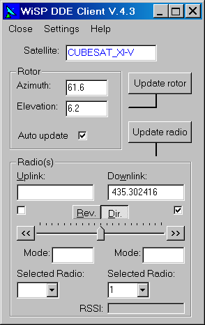
Figure 11. WispDDE main window
Finally, connect the Doppler Tuning Box to the PC, and the Doppler Tuning Box to the radio. The green LED will flash every time the Doppler Tuning Box changes the frequency of the radio. The radio will now follow the frequency generated by the satellite tracking sofware. The downlink frequency in figure 11 is 435.302416 MHz and the radio will be set to 435.302.4 MHz
Download
You can download the source code for this project
by going to the download page. This page
also contains video clips.
Troubleshooting
Hints for troubleshooting can be found on the
troubleshooting
page.
Credit
Thank you to Alex, EA4BFK, who responded to my
question on the AMSAT-BB mailing list and presented his idea to me.