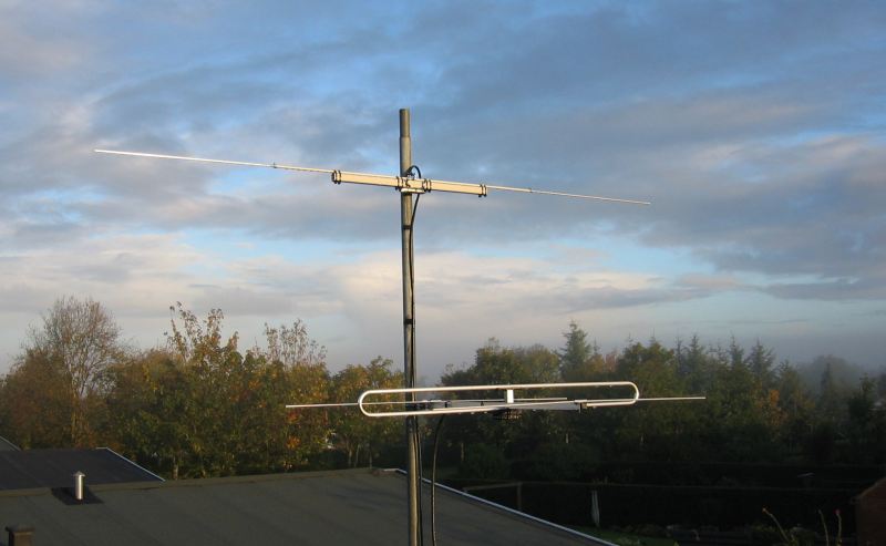
Upper antenna: 70 MHz dipole;
Lower antenna: Vargarda 3EL2 yagi for the 2 meter band.

Center of the 70 MHz dipole.
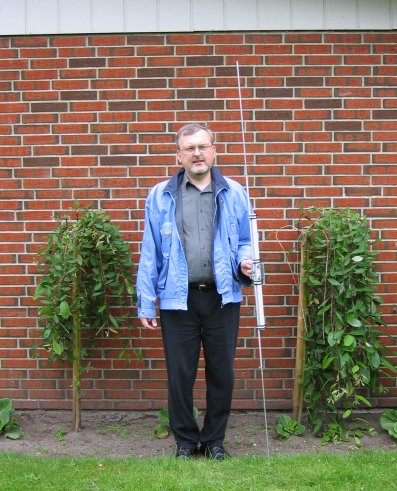
The 70 MHz dipole is slightly taller than me (OZ1BXM).

Upper antenna: 70 MHz dipole;
Lower antenna: Vargarda 3EL2 yagi for the 2 meter band.

Center of the 70 MHz dipole.

The 70 MHz dipole is slightly taller than me (OZ1BXM).
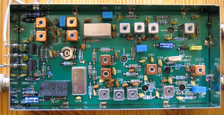
The finished OZ-transverter.
The upper row of components form the RX chain, the center row the LO, while the lower row components compile the TX chain. The PCB is built into a sheet-metal box. Three BNC sockets are fitted for RF-signals: 28 MHz input/output at the left; 70 MHz input at the upper right; and 70 MHz output at the lower right. Feed-through capacitors are fitted (left box wall) and they decouple the supply voltage input, the PTT voltage input, and the antenna relay voltage output.
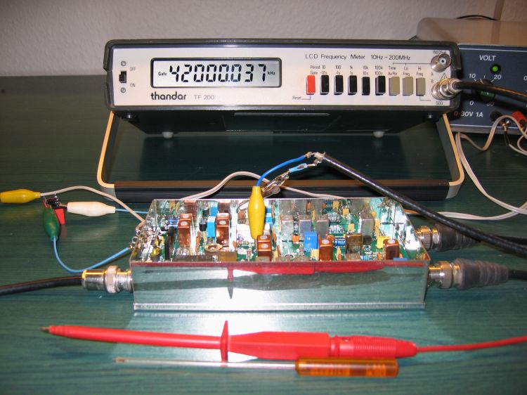
Adjusting the Local Oscillator.
The snapshot above shows my working table on a Monday evening while adjusting the local oscillator. The Thandar counter displays the frequency of the 42 MHz LO.
