1296 MHz transverter

This page describes my effort to become QRV on the 1296 MHz band. I'll start with building a transverter: Kuhne MKU13G2B (kit). 

Building a 1296 MHz transverter

Kuhne 23 cm transverter
Kuhne 23 cm transverter.
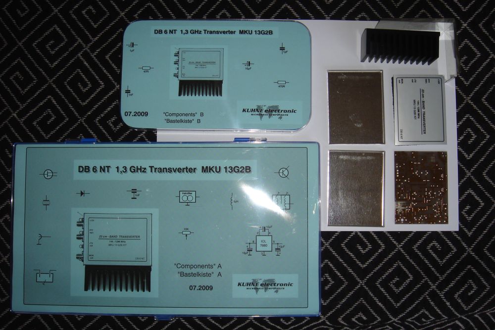
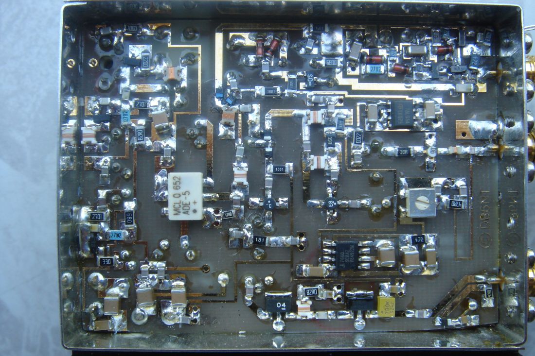
Transverter kit
I have decided to build the Kuhne MKU 13G2B kit. The Kuhne transverter covers 1296-1298 MHz and the IF is at 144-146 MHz. This kit was presented at the VHF-day in Ringsted, Denmark in February 2011 and recommended by OZ2LD Christian, who said "This kit is the cheapest and easiest way to become QRV on 23 cm".

Assembly
This kit is for experienced builders only. Excellent soldering skills are required. Experience with SMD components is a must.
The transverter is assembled in sections, and each section is tested before moving to the next one.
  • Use a 30 W soldering iron and 1 mm solder for the shield metal and coil cans. 
  • Use a temperature controlled soldering iron set for 350 degrees C and 0.5 mm solder for the SMD. Choose the tip size carefully.
  • The above mentioned soldering iron must be ESD-safe and connected to an ESD mat. 
  • An ESD mat is used whenever ESD sensitive devices are handled or soldered. 
  • A flux pen is used for applying non-corrosive flux when resoldering copper islands or components.
  • Some capacitors have a big footprint. The big capacitors are marked 1206.
  • Some resistors have a small footprint. The small resistors are marked with a star * (size 0805).
  • The 12 nH inductor in the RX near MGF4918D is difficult to solder. Pre-tinning its tiny solder pads may help.
  • Thread for the 12 x M2 screws is made by a threading tool. I bought a thread tool kit on ebay.de (sold by gewindebaron-neuwaren).
  • The 7808 is fastened to the tin-plate box using a M3 bolt and nut.
  • The hole diameter for an SMA-female connector is 4 mm.

Alignment values
The table below displays the DC voltages, that I measured on my 1296 MHz transverter. The voltmeter was connected to ground at the transverter screen. TX OUT was terminated with a 50 ohm dummyload. RX IN was connected to a 50 ohm signal source. The power supply was 12.0 V DC.

Measured atRX [V]TX [V]Remarks
7808 input12.012.0 During TX, the voltage may decrease due to voltage loss in the cables between power supply and transverter.
7808 output7.987.98 
7809 input0.111.2  
7809 output0.08.96  
78L05 output4.970.0  
ICL7660 output-4.930.0  
MGF4918 gate-0.330.0    
MGF4918 drain2.000.0    
BAR64 anode0.800.0One diode in the diode switch near ADE-5 IF port. This diode conducts in RX. 
BAR64 anode0.00.80Another diode in the diode switch near ADE-5 IF port. This diode conducts in TX. No IF signal applied.
SST310 drain7.477.47
SST310 source1.051.05
SST310 gate0.00.0
M15.615.61Oscillator was tuned for minimum voltage at M1.
M26.716.71Bandfilter F1 (384 MHz) was tuned for minimum voltage at M2.
BAR63 anode0.860.0One diode in the diode switch near ADE-5 RF port. This diode conducts in RX.  
BAR63 anode0.00.86Another diode in the diode switch near ADE-5 RF port. This diode conducts in TX. No IF signal applied.
180 ohm/1 nF junction
near F5
0.03.24 No IF signal applied.
GALI4 input0.02.58GALI4 was replaced by SNA-586. No IF signal applied.
GALI4 output0.0
4.75GALI4 was replaced by SNA-586. No IF signal applied.
AH102A input0.00.0
No IF signal applied.
AH102A output0.08.90No IF signal applied.
MON out0.01.00The IF transceiver transmits 3 W FM at 144.5 MHz into the IF port.
The measured MON out voltage corresponds to 100 mW at 1296.5 MHz.

How to adjust the transverter's RX chain using the "Milli-Beacon"signal source:
I used Yaesu FT-847 as IF transceiver. Connect the IF transceiver (144 MHz) to the transverter. Insert a 26 dB attenuator between the signal source and the transverter's RX IN to prevent receiver overload. If you don't own a 26 dB attenuator, use a value close enough, for example 30 dB.
1. The signal source is turned off. Set the IF transceiver's mode to USB. Adjust the RX gain potmeter so that when the transverter is turned on, a slight rise in noise is heard in the IF transceiver.
2. Turn on the signal source and locate the signal in the IF transceiver. The transverter's crystal oscillator coil is tuned for maximum output (minimum voltage at M1). 
3. Adjust F3 and F4 for maximum signal (use the S-meter of the IF transceiver).   
4. F2 may be adjusted to gain a higher S-meter reading, but it should be readjusted together with the TX chain.    

How to adjust the transverter's TX chain
Connect a dummy load to TX out. Ground the PTT terminal and check the DC values of 180 ohm/1nF, GALI4 output, and AH102 output. Set TX gain to minimum and apply a 3 W carrier at 144.5 MHz. Now follow the alignment instruction in the user handbook.   

Problems

ProblemSolution
The transverter's crystal oscillator stopped when mounted outdoors.When the problem occured, the crystal oscillator was aligned to the right frequency  I trimmed the oscillator for maximum output instead. Now the problem is gone, but the transverter operates 7 kHz below the right frequency.    
Bad coax between transverter and 144 MHz IF transceiver. Rocking the connector created noise and loud sounds.  The coax was cheap RG58 with BNC connectors. The problem was solved by upgrading to brand new Aircell 5 double screened coax cable and new connectors. 

Photos

Click on any image to enlarge. 

Kuhne MKU 13G2B KIT - transverter kit for 1296 MHz

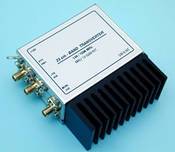
Kuhne MKU13G2B kit - a transverter kit for 1296 MHz.

Finished transverter - Top view

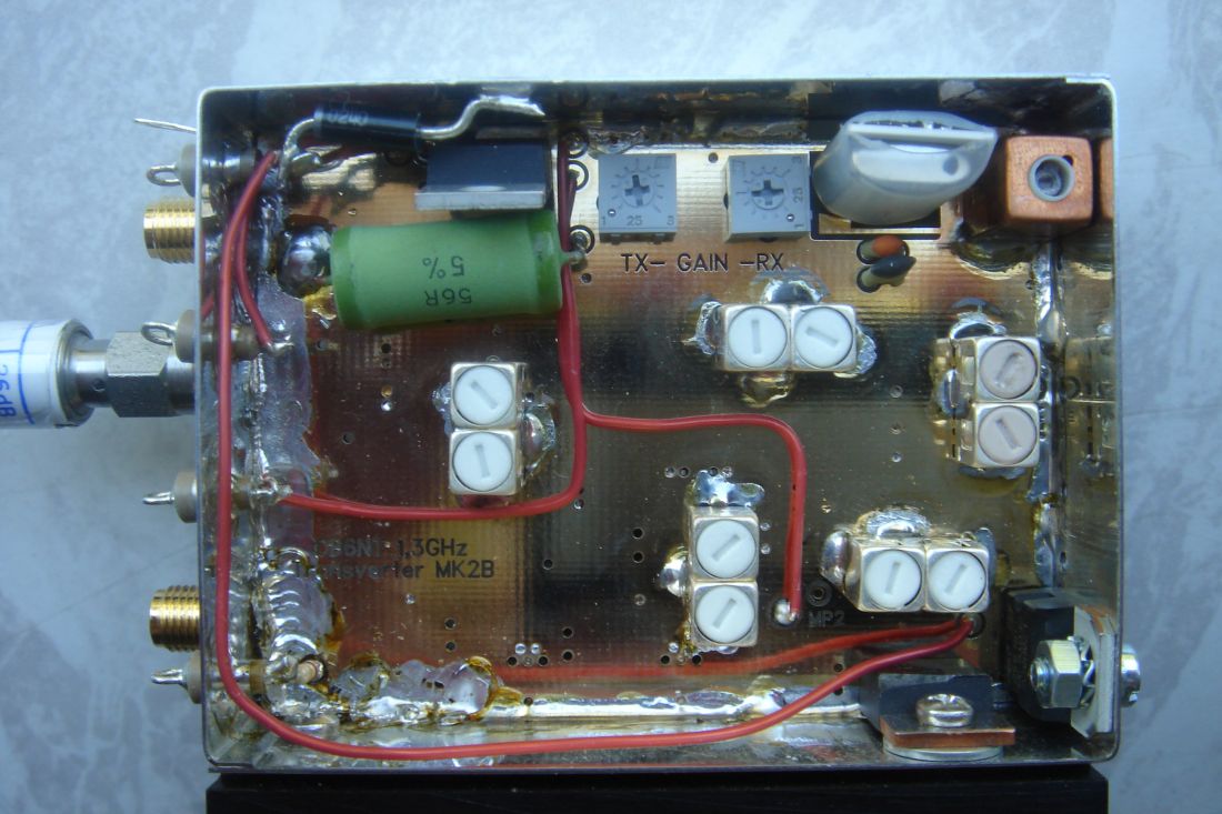
Finished transverter - top view.

Finished transverter - bottom view

Finished transverter - bottom view.


44 element yagi for 23 cm
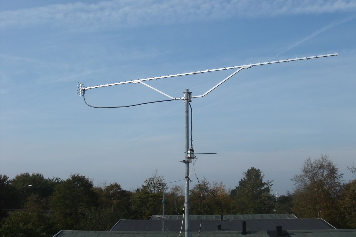
44 element yagi for the 23 cm band.

The antenna is SHF 2344 from Wimo. This 44 element yagi antenna is easy to assemble as all elements are mounted at the factory. The reflector has 8 elements. The cable between antenna and transverter is Ecoflex 10 terminated with N-connectors. The 23 cm transverter is visible below the antenna (housing will be improved later).

Written 03-Oct-2011 by OZ1BXM Lars Petersen. Latest revision Febr 2020.

Home